Self-aligning scanning probes for a scanning probe microscope

Inactive Publication Date: 2008-01-24
NANOWORLD
View PDF6 Cites 9 Cited by
  • Summary
  • Abstract
  • Description
  • Claims
  • Application Information

AI Technical Summary

Benefits of technology

[0011]The alignment elements of the support element and of the holding element interact by making positive contact. They may face each other, or may be staggered relative to each other. Depending on their arrangement it is possible to choose a complementary design of the alignment elements, specifically a mirror-image design, or to design only individual and corresponding contact surfaces to have a matching design. The alignment elements may be of recessed and / or raised design, of any cross-sectional shape, and may have the same or different lengths. Preferably, the raised alignment elements are higher than the recessed alignment elements are deep, thereby facilitating the self-alignment.
[0012]The precision of the lateral alignment is ensured, for example, by V-shaped ridges on the support element that are arranged perpendicular to each other, and by exactly matching V-shaped grooves on the back side of the scanning probes. The height of the ridges and the depth of the grooves are selected so that the scanning probe coupled with the support element rests only on the ridges, with the V-shape of the alignment elements causing an optimal alignment in all three spatial directions. The alignment elements of the holding element and of the support element interact on the basis of the lock-and-key principle. When the holding element is placed on the support element of the scanning probe and subjected to mechanical contact pressure, the scanning probe is aligned with high reproducibility.
[0015]This has the effect that, regardless of the length of the micro cantilever beam, the scanning tip will always be at the exact same distance from the reference point of the holding element, and therefore from the alignment elements of the holding element that are linked to the reference point. This makes it possible to vary the length of the micro cantilever beam without changing the position of the alignment elements of the holding element relative to the scanning tip. Due to the identical distance from the reference point, the scanning tip also will always have the exact same distance from the reference point of the support element, and therefore from the corresponding scanning position of the sample.

Problems solved by technology

Any contact between the scanning probe and the sample will usually damage the scanning probe to an extent that it is no longer usable.
In atomic force microscopy where the scanning tip of the scanning probe contacts the sample surface during the scanning process, the scanning tip is subject to constant wear due to the mechanical interaction.
As a rule, this is a difficult process because after every change of the scanning probe, the detection system of the scanning probe microscope must be realigned to the exact position of the scanning tip at the free end of the micro cantilever beam so that the deflection of the beam can be detected.
The application of scanning probe microscopes also poses the problem that after the replacement of the scanning probe the scanning tip must be aligned relative to the sample in such a way that the measurement that was interrupted by the probe replacement process can be continued at the exact spot where it was interrupted.

Method used


Image

  • Self-aligning scanning probes for a scanning probe microscope
  • Self-aligning scanning probes for a scanning probe microscope
  • Self-aligning scanning probes for a scanning probe microscope

Examples


Embodiment Construction

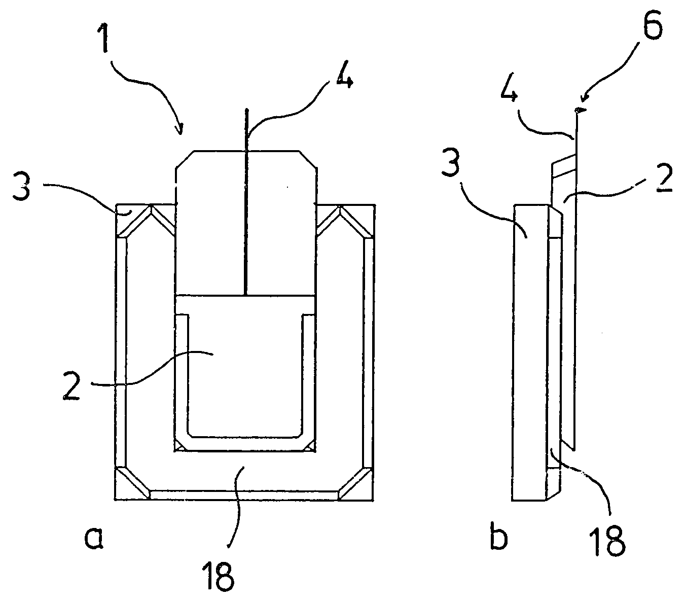
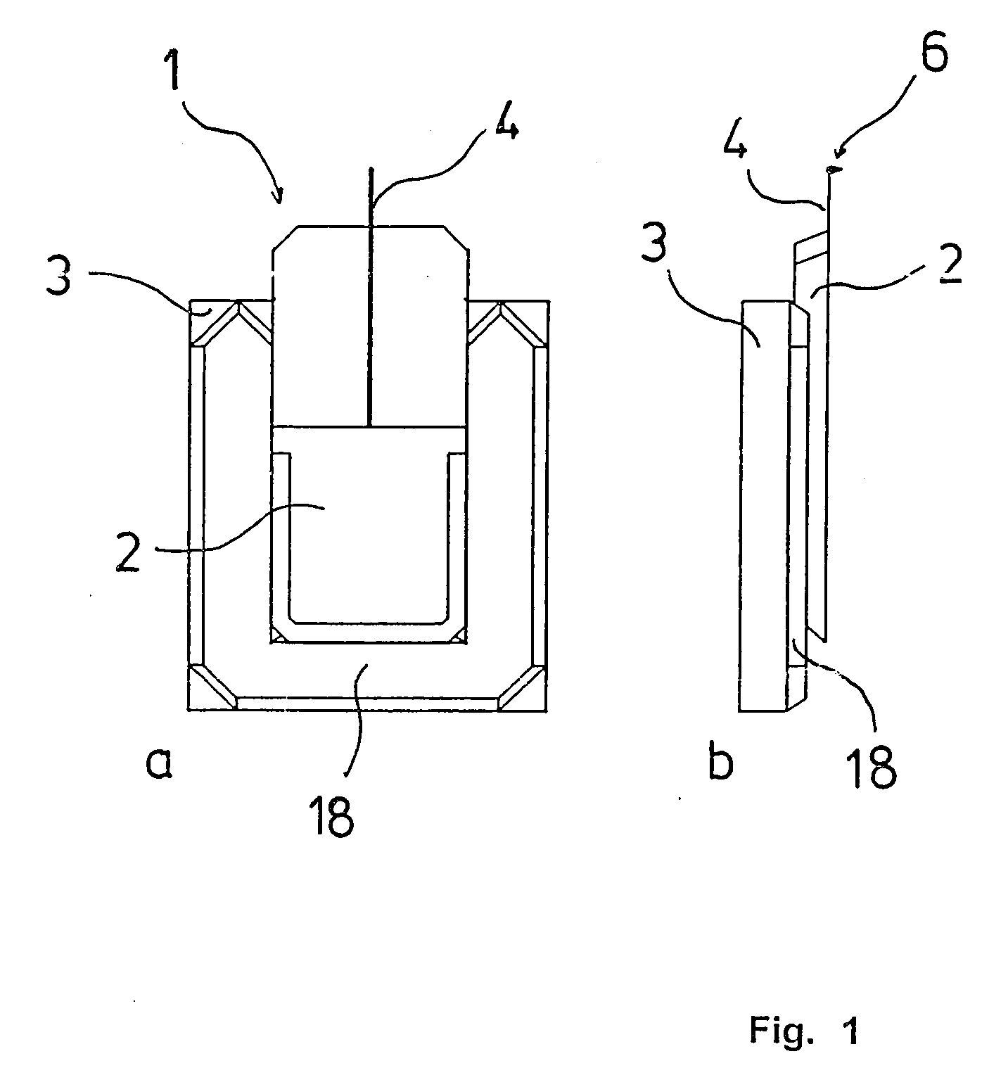
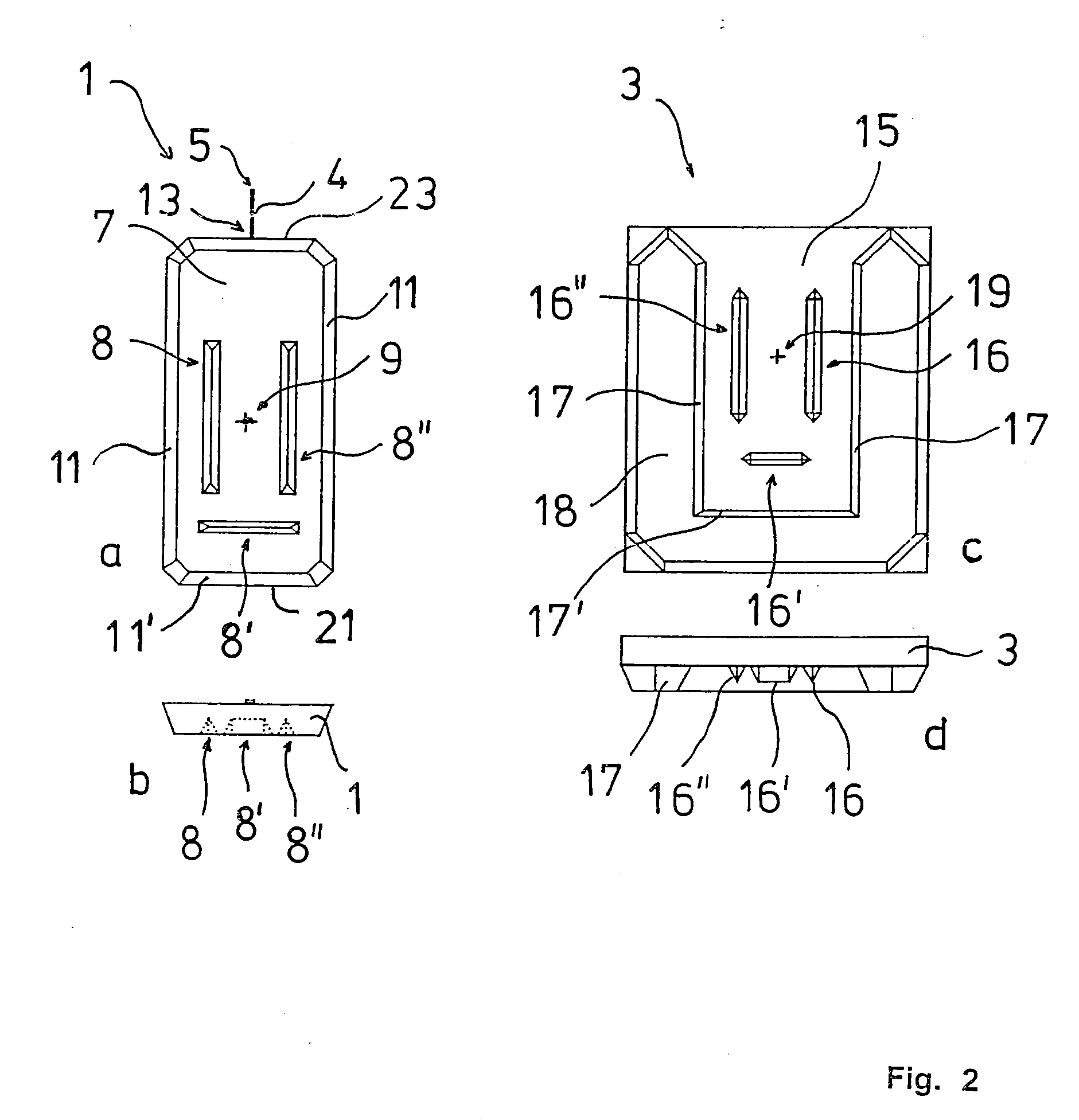
[0031]FIG. 1 shows a scanning probe 1 in accordance with the invention whose holding element 2 is coupled with a support element 3 of a probe holder (not shown). Arranged behind the holding element 2, it has a micro cantilever beam 4 at whose one end 5 a scanning tip 6 rises perpendicular to the micro cantilever beam 4, as shown in FIG. 1a. This scanning tip 6 serves to scan a sample (not shown). The support element 3 is secured in position on the probe holder, and the scanning probe 1 is connected non-permanently to the support element 3 via the holding element 2. The support element 3 and the holding element 2 are essentially square and have recesses and raised sections serving as alignment elements 8, 8′, 8″, 16, 16′, 16″, 18, as shown in FIG. 2a to 2d, through which the support element 3 and the holding element 2 act on each other by means of positive contact.

[0032]FIGS. 2a, 2b show the scanning probe 1 without the support element 3. On the contact side 7 associated with the sup...


PUM


Abstract

Scanning probes are provided for alternative use in a scanning probe microscope. The scanning probes have micro cantilever beams of different lengths whose one end has a scanning tip for scanning a sample and whose other end has a holding element for the non-permanent attachment of the scanning probe to a support element secured in position on a probe holder, and where corresponding alignment elements are incorporated in the holding element and in the support element that align the holding element in automatically reproducible fashion relative to the probe holder when coupled with the support element. The distance between the scanning tip and a defined reference point of the holding element is constant in each case so that an alignment of the scanning probe in longitudinal direction is not necessary when the scanning probe is exchanged.

Description

PRIORITY CLAIM [0001]This application claims priority under 35 U.S.C. §119(a) to European Patent Application No. 06010813.1, filed on May 26, 2006, the entire contents of which are hereby incorporated by reference.TECHNICAL FIELD OF THE INVENTION [0002]The invention concerns scanning probes for alternative use in a scanning probe microscope where the scanning probes have a micro cantilever beam whose one end has a scanning tip for scanning a sample and whose other end has a holding element for the non-permanent attachment of the scanning probe to a support element secured to a probe holder, and where corresponding alignment elements are incorporated in the holding element and in the support element that align the holding element in automatically reproducible fashion relative to the probe holder when coupled with the support element.DESCRIPTION OF THE RELATED ART[0003]Scanning probe microscopes are well known. They serve to scan the surface of a sample with resolutions down to the at...

Claims


Application Information

Patent Timeline
IPC IPC(8): G02B21/00G01Q10/00G01Q70/02
CPCG01Q70/02B82Y35/00
Inventor SULZBACH, THOMASDETTERBECK, MANFREDBURRI, MATHIEURICHTER, CHRISTOPHLUDGE, HANS-JURGEN
Owner NANOWORLD
Why Eureka
Try Eureka