Method and apparatus for coherently combining multiple laser oscillators

a laser oscillator and coherent technology, applied in the field of lasers, can solve the problems of high brightness produced by a single laser source, limited power or energy per unit volume that can be extracted or stored, and expensive apparatus described by abrams, and achieve the effect of high intensity laser outpu

Inactive Publication Date: 2008-01-24
HRL LAB
View PDF28 Cites 8 Cited by
  • Summary
  • Abstract
  • Description
  • Claims
  • Application Information

AI Technical Summary

Benefits of technology

[0016] Embodiments of the present invention provide a method and apparatus for coupling a plurality of lasers and utilizing interactions between the plurality of lasers to form a coherent optical output. Embodiments of the present invention preferably utilize fiber lasers with sufficient connectivity to produce a higher intensity laser output. The coupling of the fiber lasers may be accomplished by using any of a number of techniques well known in the art. Preferred embodiments of the present invention may use devices that are fabricated using relatively standard optical fiber melting, combining, and pulling techniques to couple the fiber lasers.

Problems solved by technology

Producing high brightness from a single laser source is generally limited by the fact that there is an inherent limit to the power or energy per unit volume that can be extracted from or stored in a lasing medium.
Hence, the apparatus described by Abrams may be expensive and difficult to implement.
However, the power output of a single fiber laser without amplification or other power increasing techniques is relatively low.
However, the additional circuitry required to detect and compensate for the relative optical phase shifts increases the complexity of the system disclosed by Brosnan.
Also, fiber amplifiers are generally less efficient than fiber oscillators (lasers).
Hence, the system disclosed by Brosnan would be considered less efficient than a system based on a plurality of fiber oscillators.
However, this configuration does not provide for phase-locking between the light propagating in each of the cores.
A key problem with multiple-core fiber oscillator systems, such as the system disclosed by Scifres, is heat dissipation.
Hence, the power of the multiple-core fiber oscillator systems will be limited by the ability to dissipate the heat generated by the active regions away from the multiple-core fiber, similar to the way that glass rod lasers are limited in average power scaling.

Method used


Image

  • Method and apparatus for coherently combining multiple laser oscillators
  • Method and apparatus for coherently combining multiple laser oscillators
  • Method and apparatus for coherently combining multiple laser oscillators

Examples


Embodiment Construction

[0033] The present invention will now be described more fully hereinafter with reference to the accompanying drawings, in which preferred embodiments of the invention are shown. This invention may be embodied in many different forms and should not be construed as limited to the embodiments set forth herein. Further, the dimensions of certain elements shown in the accompanying drawings may be exaggerated to more clearly show details. The present invention should not be construed as being limited to the dimensional relations shown in the drawings, nor should the individual elements shown in the drawings be construed to be limited to the dimensions shown.

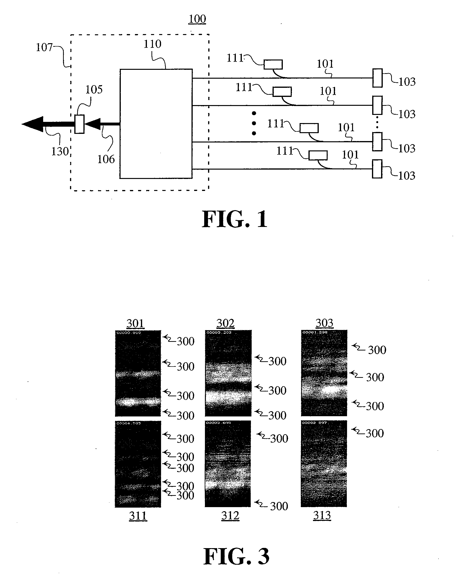
[0034]FIG. 1 shows a generalized embodiment of a laser apparatus 100 according to the present invention. In FIG. 1, a plurality of fibers 101 with regions comprising a lasing medium are coupled together at one end of a combiner 107 having a coupler 110 and a second reflector 105. A first reflector 103 is disposed at the other end of e...


PUM


Abstract

A laser apparatus having multiple laser devices coupled together. The laser devices comprise optical fibers with laser active regions. Each of the fibers has a reflector disposed at one end and is connected to a combiner on the other end. A laser pump device for each fiber provides pump energy to the laser active regions. Light propagating in the fibers interacts so as to form inphase states. The array of fibers may be coupled either in pairs or altogether between the reflector and the laser active region.

Description

CROSS-REFERENCE TO RELATED APPLICATIONS [0001] This patent application is related to and claims the benefit of co-pending U.S. Provisional Patent Application Ser. No. 60 / 441,027, filed on Jan. 17, 2003 and titled “Method and Apparatus for Coherently Combining Multiple Laser Oscillators”. The disclosure of U.S. Provisional Patent Application No. 60 / 441,027 is incorporated herein by reference in its entirety. [0002] The subject matter of the present application may also be related to the co-pending U.S. Provisional Patent Application Ser. No. 60 / 441,026, filed on Jan. 17, 2003 and titled “Method and Apparatus for Combining Laser Light”. The contents of this U.S. Provisional Patent Application Ser. No. 60 / 441,026 are incorporated by reference herein in their entirety. [0003] The subject matter of the present application may also be related to the co-pending U.S. Patent Application Ser. No.______ (Attorney Docket No. B-4759NP 621649-7), filed of even date herewith and titled “Method and...

Claims


Application Information

Patent Timeline
Patent Type & Authority Applications(United States)
IPC IPC(8): G02B6/42G02B6/04G02B6/28G02B6/34H01S3/067H01S3/094H01S3/23
CPCG02B6/04G02B6/2808H01S3/067H01S3/2383H01S3/094042H01S3/10092H01S3/0675
Inventor ROGERS, JEFFREYMINDEN, MONICABRUESSELBACH, HANS W.JONES, CRIS
Owner HRL LAB
Why Eureka
Try Eureka