Universal electrical wiring component

a technology of universal electrical wiring and components, applied in the direction of electrical apparatus construction details, machine supports, coupling device connections, etc., can solve the problems of increasing reducing the number of skus and associated inventory and planning headaches, and reducing installation costs. , the effect of reducing the number of skus and reducing the number of specifications

Inactive Publication Date: 2008-01-24
BAUM FAMILY TRUST DTD 1 11 2001 +143
View PDF99 Cites 45 Cited by
  • Summary
  • Abstract
  • Description
  • Claims
  • Application Information

AI Technical Summary

Benefits of technology

[0005] A universal electrical wiring component advantageously combines an adjustable, modular mount with modular electrical devices to reduce installation costs over conventional wiring in much the same manner as a typical prefabricated system. Because a universal electrical wiring component is modular, a limited number of such components can be combined and configured as a substitute for many conventional assemblies. This significantly reduces the number of SKUs and associated inventory and planning headaches. Because a universal wiring component is adjustable, it greatly reduces specification requirements and eliminates the possibility of assembly errors associated with custom prefabricated parts. A universal electrical wiring component also advantageously accommodates design changes including the location and the type of an electrical distribution point and the function and color of an installed electrical device. Testing of the wiring system can be accomplished at the rough-in phase while walls are open rather than the trim-out phase. Trim-out can be completed without touching a wire. Devices can finish flush with the wall every time.

Problems solved by technology

Conventional electrical wiring installation is a logistical nightmare of schedules, inventory, design changes and rework to correct design and installation errors and product defects.
Such prefabricated electrical systems, however, do not solve all of the logistical problems associated with electrical wiring system design and installation and create additional ones.
Each prefabricated part is custom made so there is much room for mistakes to be made in the specification and assembly process.
If an electrician opens the SKU to fix a problem inside, the product warranty may be void.

Method used


Image

  • Universal electrical wiring component
  • Universal electrical wiring component
  • Universal electrical wiring component

Examples


Embodiment Construction

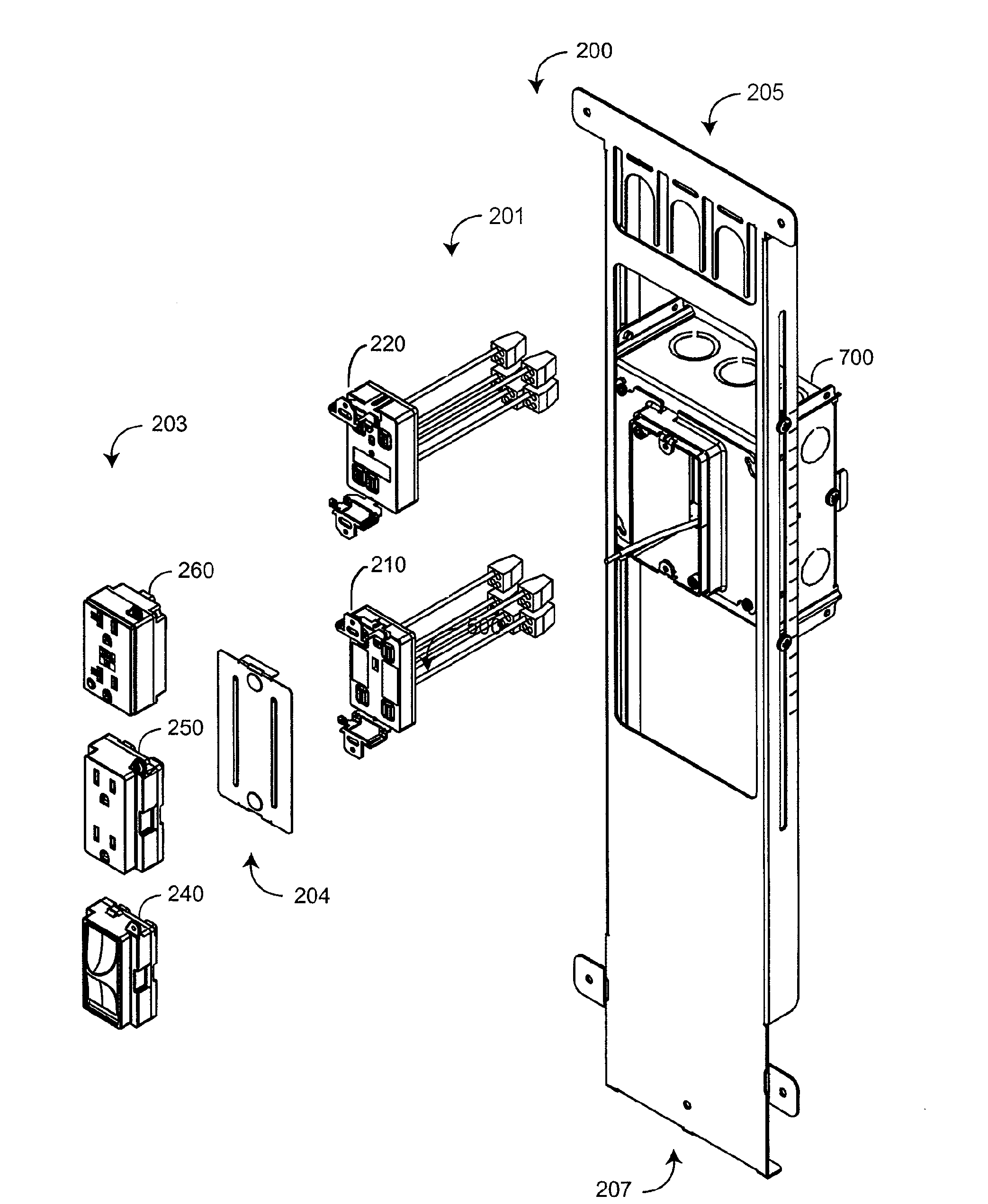
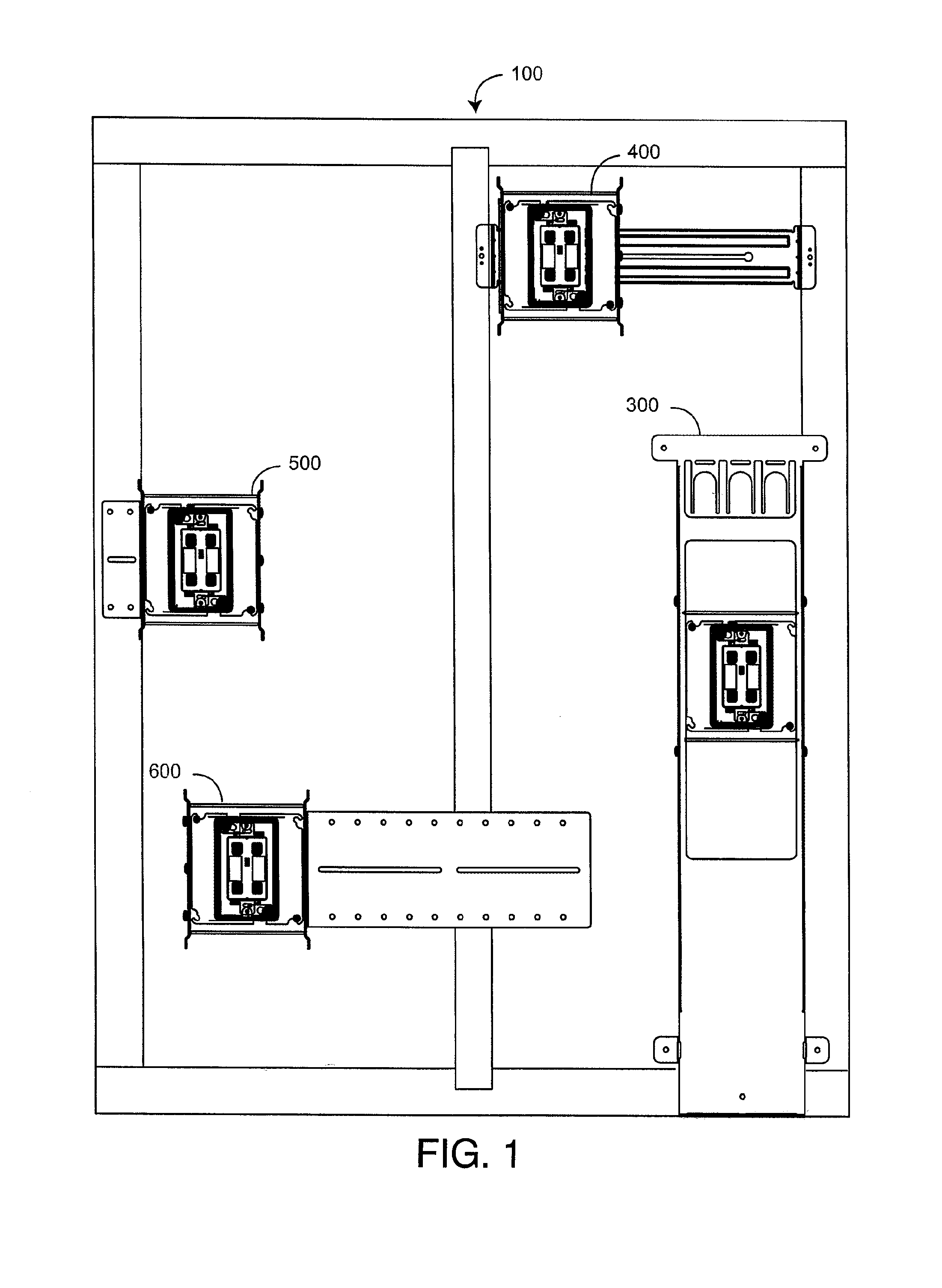
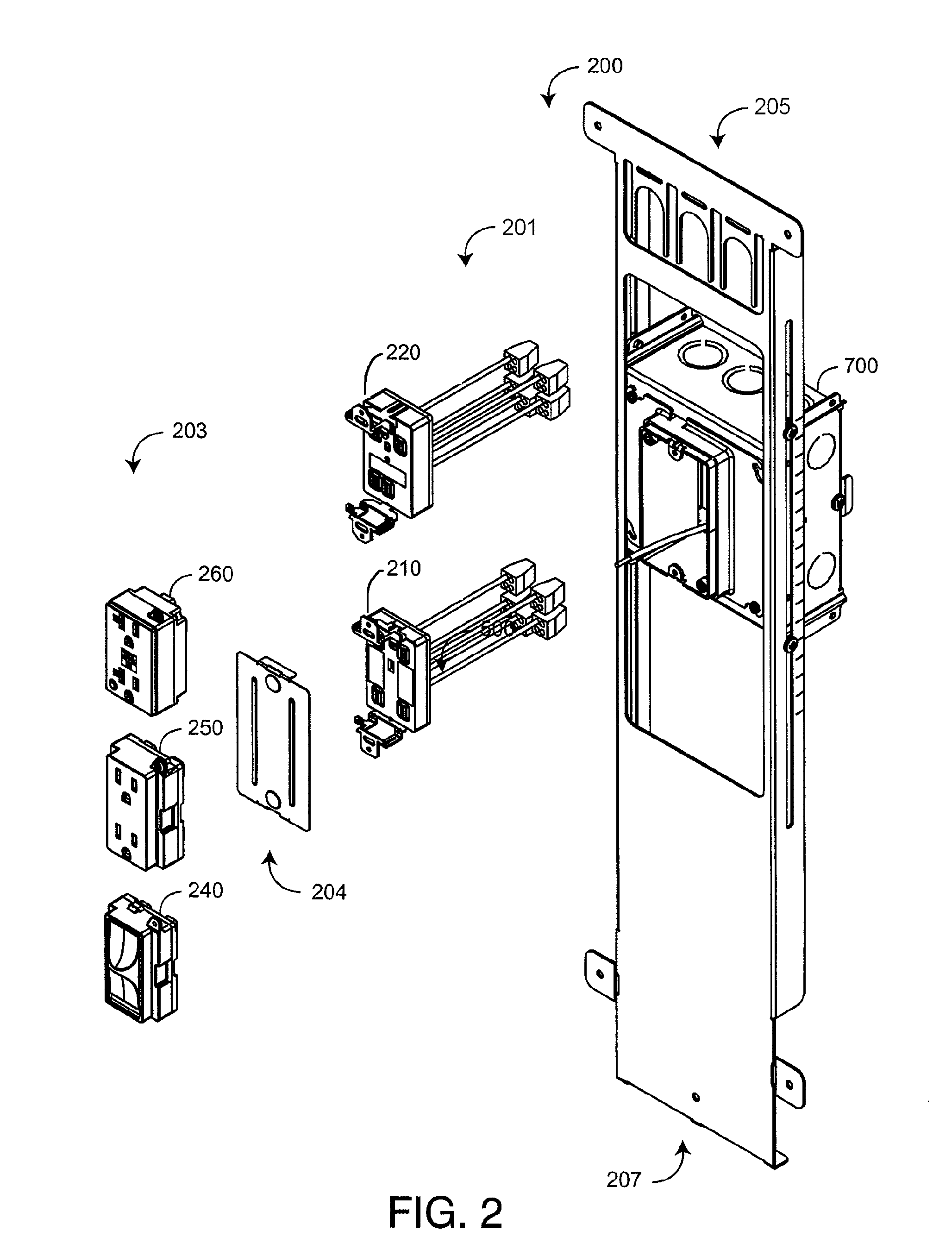
[0020]FIG. 1 illustrates a modular integrated wiring system 100 utilizing universal electrical wiring component embodiments 300-600. A floor bracket component 300, a stud bracket component 400, a box bracket component 500 and an extended box bracket 600 are included, providing adaptability for different electrical power distribution designs. Each wiring component 300-600 provides mounting flexibility by adjusting to various wall dimensions, stud configurations, and electrical distribution point locations. Specifically, each component 300-600 has an adjustable depth into the wall, guaranteeing a flush finish with the wall surface at every electrical distribution point. In addition, the floor bracket component 300 provides an adjustable height. The stud bracket component 400 can be positioned at any height and provides an adjustable distance between studs. The box bracket component 500 can be positioned at any height, and the extended box bracket component 600 can be positioned at any...


PUM


Abstract

A modular electrical wiring component comprises a wiring module having a wiring portion for coupling to a source of electrical power and a user-accessible portion configured to accept and provide electrical power to a functional module that provides a selected electrical distribution function, wherein the wiring module is configured to accept the functional module without access to the wiring portion. The modular electrical wiring component also comprises an adjustable plaster ring configured to couple to the wiring module and to an electrical junction box, wherein the adjustable plaster ring provides a variable distance between the electrical junction box and the wiring module.

Description

CROSS-REFERENCE TO RELATED APPLICATIONS [0001] This application is a continuation of co-pending U.S. application Ser. No. 10 / 924,555 filed Aug. 24, 2004 and entitled “Universal Electrical Wiring Component,” which claims priority from U.S. Provisional Application No. 60 / 552,546 filed Mar. 13, 2004 and entitled “Modular Integrated Wiring System,” both of which are incorporated by reference in their entirety.BACKGROUND OF THE INVENTION [0002] Conventional AC electrical systems are comprised of a junction box and an electrical device, such as an outlet or switch, installed within the box. During a rough-in phase of construction, power cables are routed through building framing to junction boxes mounted at predetermined electrical distribution locations. The power cables are fed through openings in the rear or sides of the junction boxes and folded back inside, unterminated, so as to be out of the way until the next phase. During a makeup phase, wall panels are installed and painted, and...

Claims


Application Information

Patent Timeline
Patent Type & Authority Applications(United States)
IPC IPC(8): H01R13/64
CPCH02G3/125Y10S248/906H02G3/128
Inventor GORMAN, MICHAEL P.
Owner BAUM FAMILY TRUST DTD 1 11 2001
Why Eureka
Try Eureka