

Radio communications system
- Summary
- Abstract
- Description
- Claims
- Application Information
AI Technical Summary
Benefits of technology
Problems solved by technology
Method used
Image

Examples
first embodiment
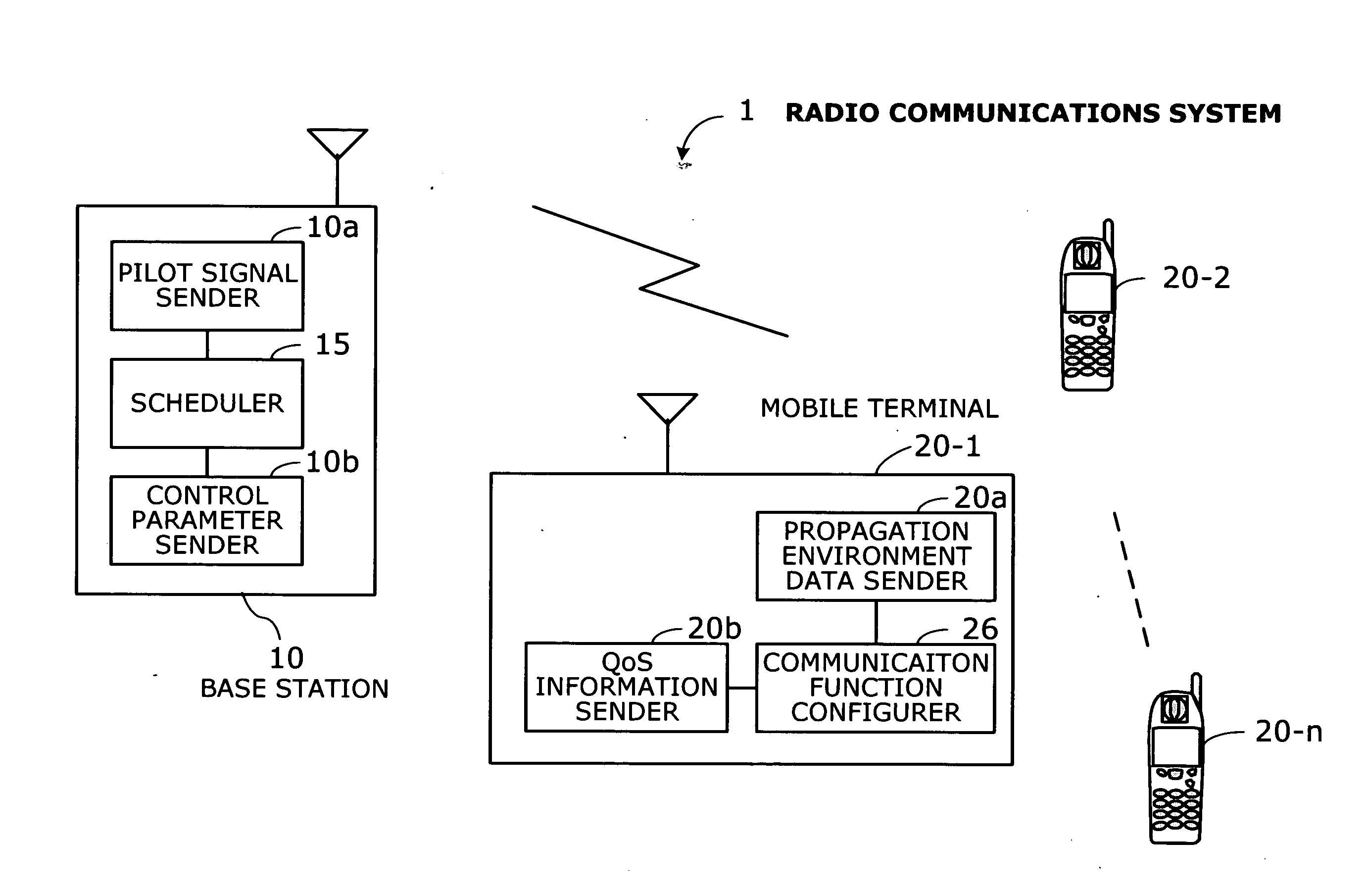
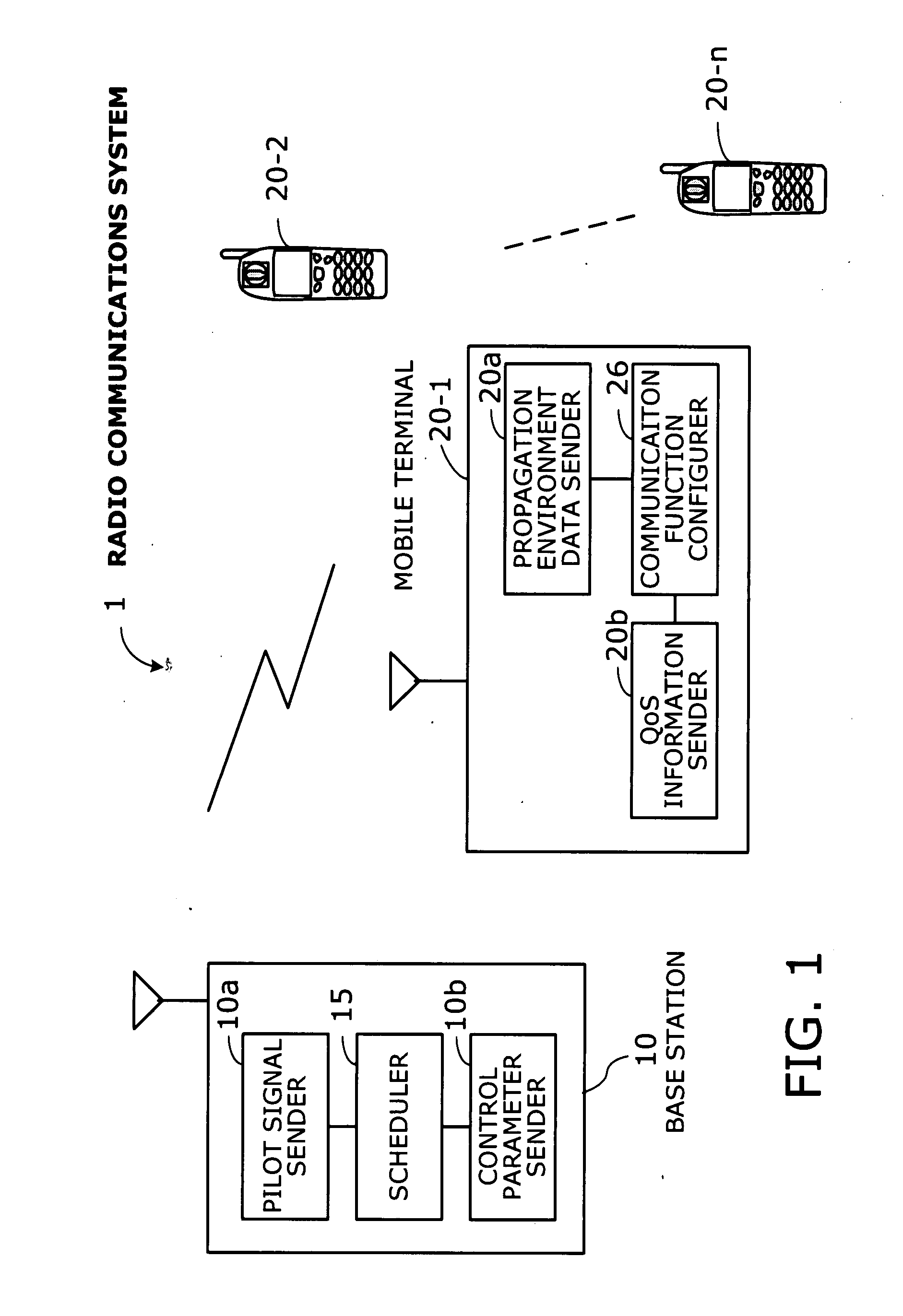
[0059] Preferred embodiments of the present invention will be described below with reference to the accompanying drawings. FIG. 1 is a conceptual view of a radio communications system 1 according to the invention. This radio communications system 1 is formed from a base station 10 and n mobile terminals 20-1 to 20-n (n≧1) connected by high-speed wireless links.
[0060] The base station 10 is a radio base station that can offer a plurality (N) of different communication services at a time. The base station 10 includes a pilot signal sender 10a, a scheduler 15, and a control parameter sender 10b.
[0061] The pilot signal sender 10a sends pilot signals with carrier frequencies corresponding to the N different communication services. Suppose, for example, that the base station supports two communication services A and B. In this case, the pilot signal sender 10a sends two pilot signals, one with a carrier frequency fA for communication service A and the other with a carrier frequency fB fo...
third embodiment
[0194] The third embodiment, on the other hand, UEs use a single particular frequency to carry all CQIs measured with respect to N pilot signals with different carrier frequencies. For example, UEs send two CQIs corresponding to two pilot signals f1p and f2p back to the base station 10 by using an uplink channel with a particular frequency.
[0195] Therefore the base station 10 has only to watch a single frequency to receive uplink signals from UEs. The base station 10, however, needs to know from which pilot signal (or which carrier frequency) the received CQIs are derived. To this end, the responding UEs 20 encode their CQI, their status, and the like.
[0196] FIGS. 14 to 16 show code tables. Referring first to FIG. 14, the carrier frequency of each pilot signal is defined in a table T1. Each signal has a bandwidth of 5.0 MHz, and the pilot signals thus use a frequency range of 800 MHz to 820 MHz. For example, the pilot signal of 802.5 MHz is represented by a code of “00.”
[0197] Refe...
PUM
 Abstract
Description
Claims
Application Information