

Air-intake apparatus
a technology of air intake and air filter, which is applied in the direction of intake silencers for fuel, combustion air/fuel air treatment, feed systems, etc., can solve the problems of difficult reduction of intake air noise in a broader range, difficult installation and expansion of peripheral parts around internal combustion engines, etc., and achieves the effect of reducing the noise of intake air and being easy to install
- Summary
- Abstract
- Description
- Claims
- Application Information
AI Technical Summary
Benefits of technology
Problems solved by technology
Method used
Image

Examples
first embodiment
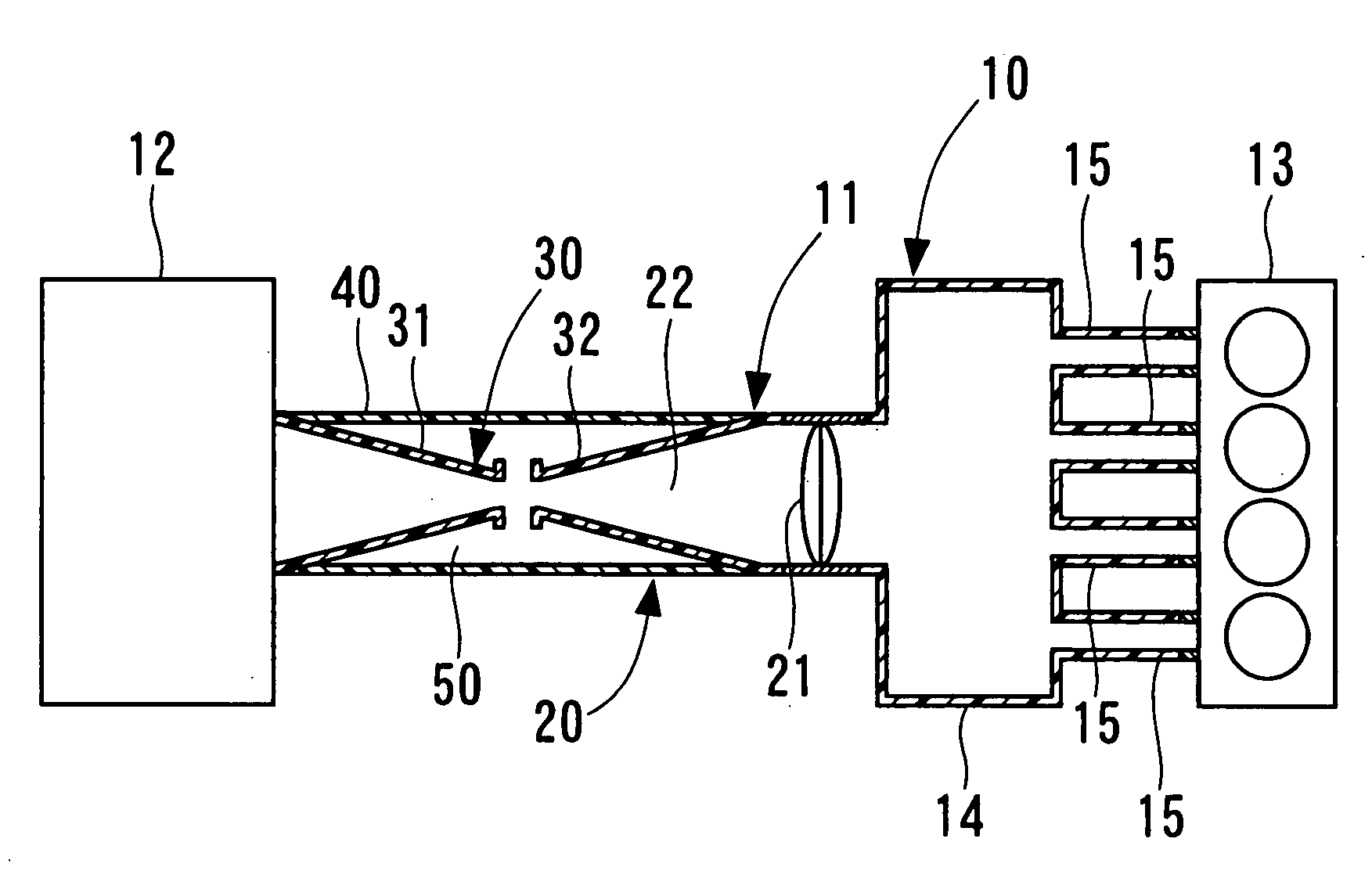
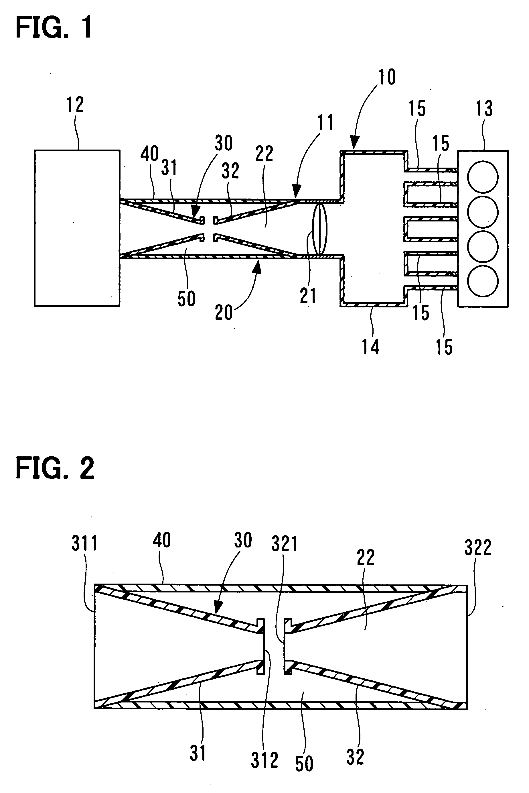
[0016]FIG. 1 shows an air-intake system, to which an air-intake apparatus according to a first embodiment of the present invention is applied.
[0017]As shown in FIG. 1, an air-intake system 10 includes an air-intake apparatus 11, an air cleaner 12, and a gasoline engine (hereafter engine) 13 as an internal combustion engine. The air-intake apparatus 11 has a surge tank 14. Intake manifolds 15 branch from the surge tank 14. The intake manifolds 15 branch out according to the number of cylinders of the engine 13, and each of the intake manifolds 15 is connected to corresponding one of the cylinders.
[0018]The air cleaner 12 is placed at an end portion of the air-intake apparatus 11, which is opposite to the other end portion, at which the engine 13 is placed. The air cleaner 12 receives an air cleaner element (not shown) inside the air cleaner 12. When air drawn into the engine 13 flows through the air cleaner 12, a foreign object is removed from the air. Air to be drawn into the engine...
second embodiment
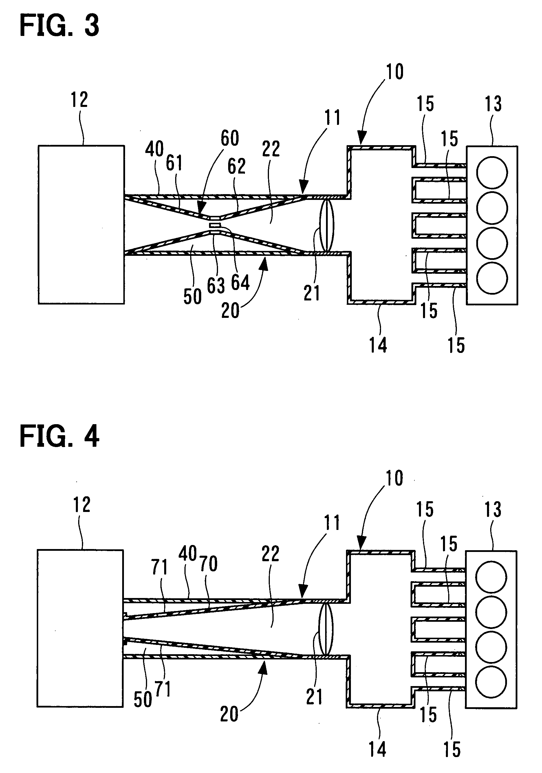
[0030]FIG. 3 shows an air-intake system, to which an air-intake apparatus according to a second embodiment of the present invention is applied.
[0031]In the second embodiment, an inner pipe member 60 is formed from one member. That is, the inner pipe member 60 has a first pipe portion 61, a second pipe portion 62, and a small diameter portion 63. The small diameter portion 63 is provided at a central portion of the inner pipe member 60 along its axial direction. The inner pipe member 60 has the first pipe portion 61 from an end portion of the inner pipe member 60 on an air cleaner 12-side toward the small diameter portion 63, and the second pipe portion 62 from the small diameter portion 63 toward an end portion of the inner pipe member 60 on a surge tank 14-side.
[0032]The first pipe portion 61 is formed in a tubular manner like a truncated cone, a diameter of which gradually decreases from its end portion on the air cleaner 12-side toward the small diameter portion 63. The second pi...
third embodiment
[0034]FIG. 4 shows an air-intake system, to which an air-intake apparatus according to a third embodiment of the present invention is applied.
[0035]In the third embodiment, a diameter of an inner pipe member 70 increases from its end portion on an air cleaner 12-side toward the other end portion on a surge tank 14-side. That is, an air-intake apparatus 11 has only a member corresponding to the second inner pipe member 32, and does not have a member corresponding to the first inner pipe member 31 in the first embodiment. A sound of intake air flowing in an intake passage 22 is reduced in a broad frequency range by the diffuser effect of the inner pipe member 70, the diameter of which increases from the air cleaner 12-side toward the surge tank 14-side. Accordingly, by providing the inner pipe member 70, which has a shape of the third embodiment, the intake air noise is reduced.
[0036]An outer circumferential side of the inner pipe member 70 is covered with an outer pipe member 40. Con...
PUM
 Abstract
Description
Claims
Application Information