Multi-layer heat insulating container

a heat insulation container and multi-layer technology, applied in the field of multi-layer heat insulation containers, can solve the problems of disadvantages of prior art cups formed of paperboard or some other materials, and inconvenient printing of advertisements or logos

Active Publication Date: 2008-01-31
HUHTAMAKI INC
View PDF13 Cites 49 Cited by
  • Summary
  • Abstract
  • Description
  • Claims
  • Application Information

AI Technical Summary

Benefits of technology

[0002]The present invention is directed to a storage container including a receptacle having a circumferential sidewall and a sleeve fixedly attached to the receptacle having a circumferential sidewall with a left edge, a right edge, and marginal portions adjacent the left and right edges wherein the edges meet to form a butt seam. The receptacle sidewall and the sleeve sidewall encompass an insulating layer therebetween. The insulating layer includes a first edge and a second edge wherein the first and second edges do not extend under the marginal portions such that the insulating layer has a smaller circumference than that of the sleeve sidewall.

Problems solved by technology

Polystyrene foam containers are known and have substantial heat-insulating properties, but containers formed exclusively of polystyrene foam are not environmentally friendly and it is difficult to print an advertisement or logo thereon because foamed styrene containers are often not sufficiently smooth to accept screen printing or other types of printing.
Nonetheless, disadvantages in prior art cups formed of paperboard or some other, non-foamed, material are obvious when hot beverages, such as coffee, are being served.
For example, most disposable coffee cups are very difficult to handle for several minutes after being filled.
However, it can take a person grasping the hot cup several moments to realize that it will be uncomfortable to hold the cup until it cools, and the cup is placed on a table.
This situation is problematic with regard to “drive-thru” service since vehicle occupants are often under way again before discomfort is perceived and the options for setting the cup aside are limited.

Method used


Image

  • Multi-layer heat insulating container
  • Multi-layer heat insulating container
  • Multi-layer heat insulating container

Examples


Embodiment Construction

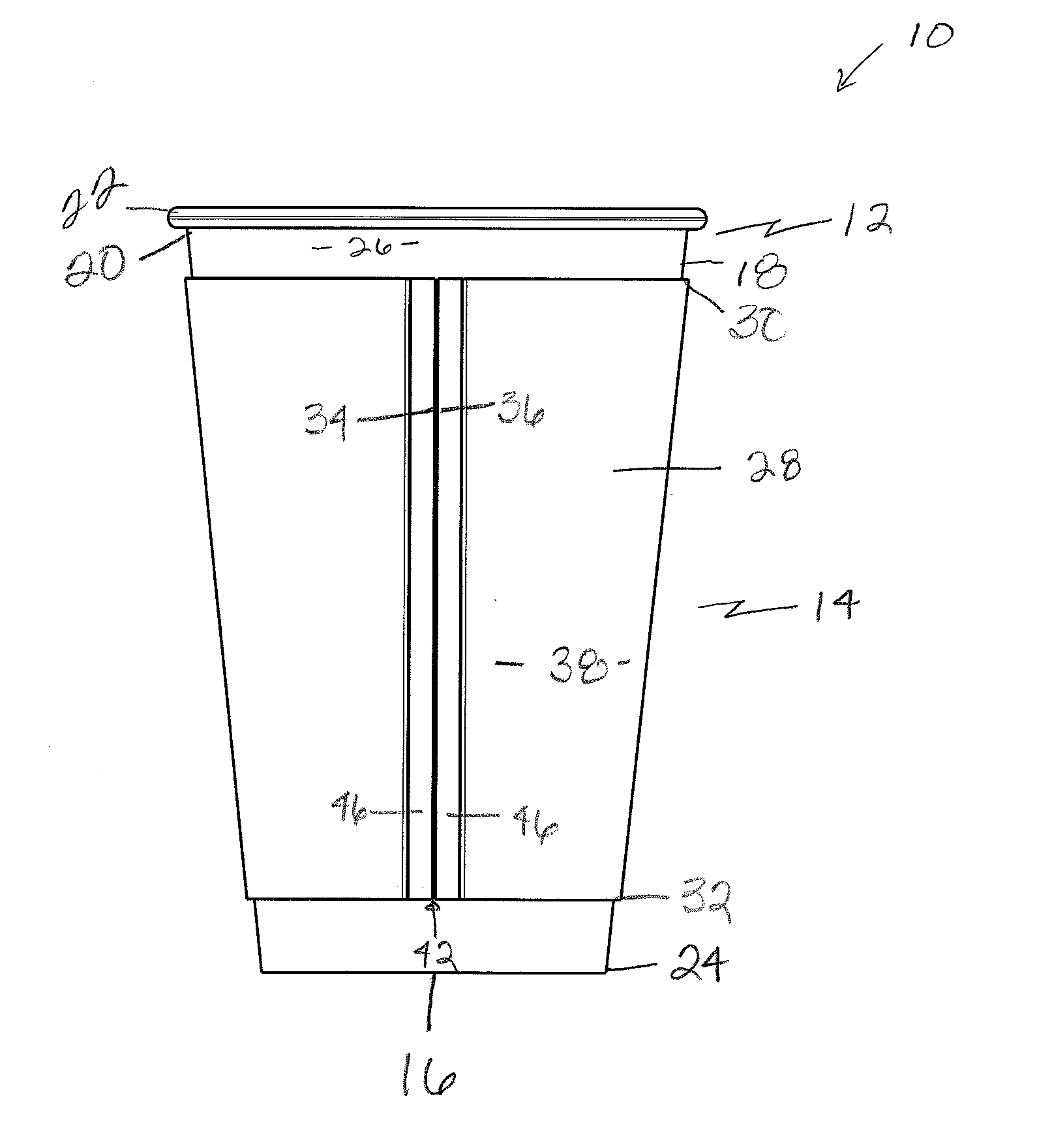
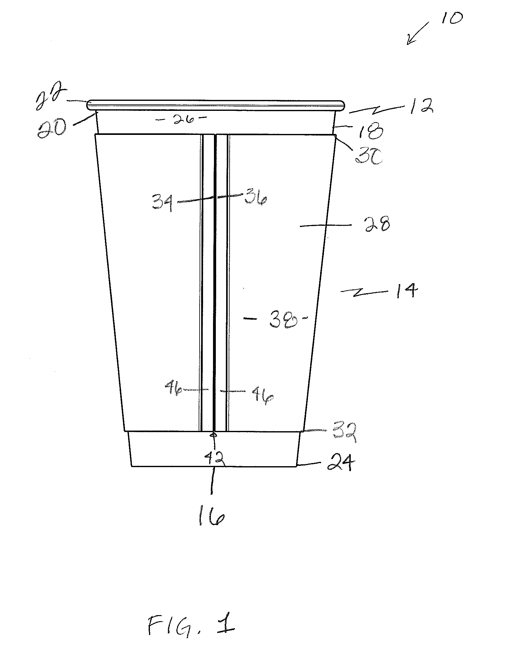
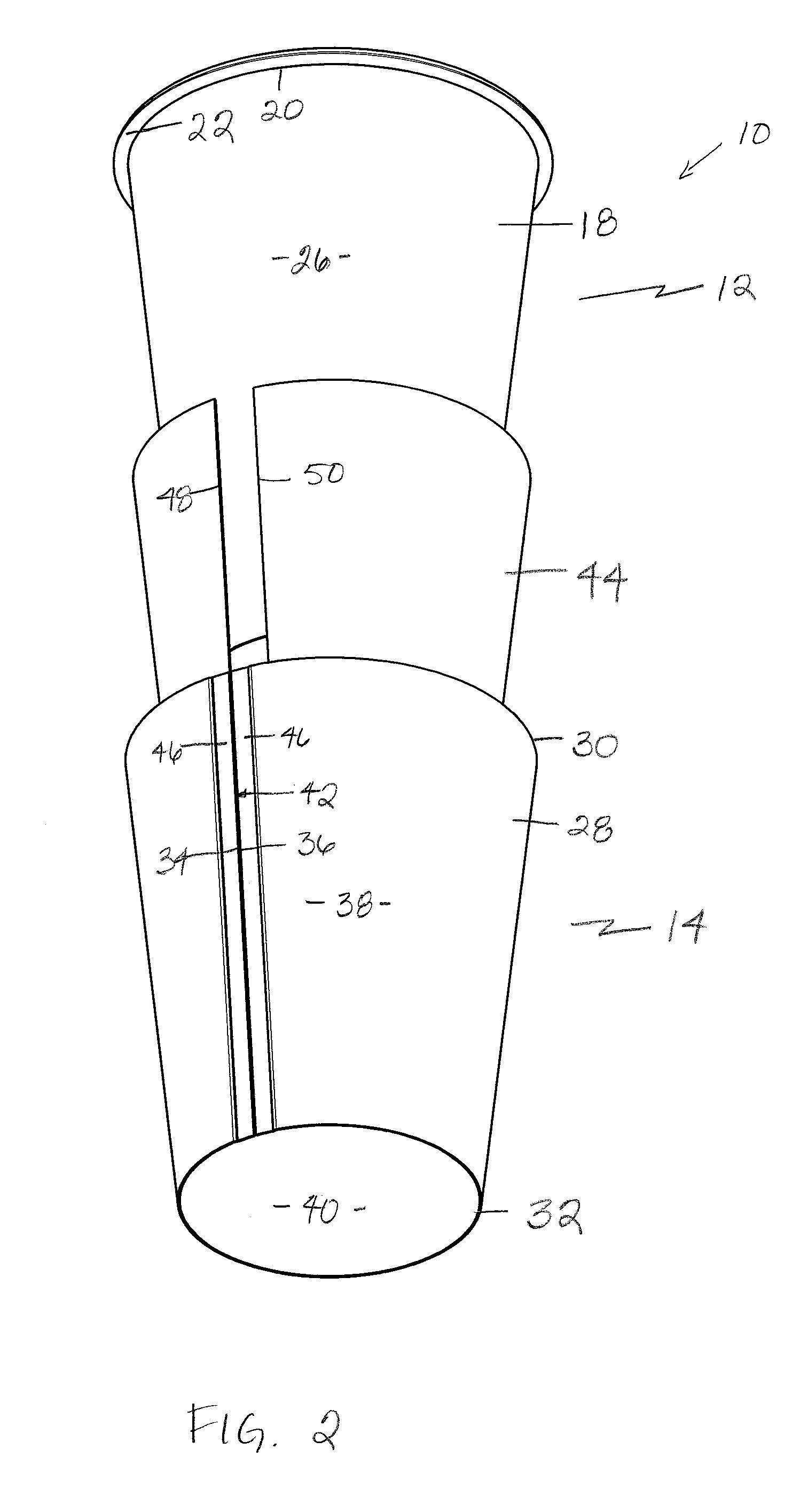
[0008]A storage container 10 embodying various features of the present invention is shown in the drawings. In a first embodiment, as shown in FIGS. 1-3, storage container 10 includes a receptacle 12 and an integral sleeve 14 fixedly attached thereto.

[0009]Turning to FIGS. 1, 2 and 3, receptacle 12 has a circular bottom portion 16 and a circumferential sidewall 18. At the top edge 20 of sidewall 18 is a rolled lip 22 to provide a comfortable drinking surface and for attaching a lid (not shown) thereon. Circular bottom portion 16 is defined between a bottom edge 24. Sidewall 18 further includes an inner surface 25 and an outer surface 26. Receptacle 12 preferably has a frusto-conical shape; that is, receptacle 12 has a circular cross-section, and the diameter of bottom edge 24 and bottom portion 16 is less than the diameter of the top edge 20 of sidewall 18. It will be appreciated by those skilled in the art that different shapes may serve equally as well and may be required by a desi...


PUM


Abstract

A storage container includes a receptacle having a circumferential sidewall and a sleeve fixedly attached to the receptacle having a circumferential sidewall with a left edge, a right edge, and marginal portions adjacent the left and right edges wherein the edges meet to form a butt seam. The receptacle sidewall and the sleeve sidewall define an insulating layer therebetween. The insulating layer includes a first edge and a second edge wherein the first and second edges do not extend under the marginal portions such that the insulating layer has a smaller circumference than that of the sleeve sidewall. A method for forming a storage container is also provided.

Description

BACKGROUND OF THE INVENTION[0001]Many types of heat-insulating containers have been used commercially to contain hot liquids such as coffee or hot chocolate. Polystyrene foam containers are known and have substantial heat-insulating properties, but containers formed exclusively of polystyrene foam are not environmentally friendly and it is difficult to print an advertisement or logo thereon because foamed styrene containers are often not sufficiently smooth to accept screen printing or other types of printing. Nonetheless, disadvantages in prior art cups formed of paperboard or some other, non-foamed, material are obvious when hot beverages, such as coffee, are being served. For example, most disposable coffee cups are very difficult to handle for several minutes after being filled. However, it can take a person grasping the hot cup several moments to realize that it will be uncomfortable to hold the cup until it cools, and the cup is placed on a table. This situation is problematic...

Claims


Application Information

Patent Timeline
Patent Type & Authority Applications(United States)
IPC IPC(8): B65D3/00B31B50/00
CPCB65D81/3874
Inventor ROBERTSON, RONALD D.MCKAHAN, WILLIAM D.
Owner HUHTAMAKI INC
Why Eureka
Try Eureka