
Liquid crystal display apparatus and light emitting unit

a technology of liquid crystal display and light emitting unit, which is applied in the direction of lighting and heating apparatus, instruments, spectral modifiers, etc., can solve the problems of image blur, reduced bit depth, and poor image display, and achieve the effect of ensuring the image display quality of the lcd apparatus

Inactive Publication Date: 2008-01-31
GIGNO TECH CO LTD
View PDF5 Cites 2 Cited by
  • Summary
  • Abstract
  • Description
  • Claims
  • Application Information

AI Technical Summary

Benefits of technology

[0013]In view of the foregoing, the invention is to provide an LCD apparatus and a light emitting unit that can allow the user to manually adjust the white balance without affecting the image display.
[0014]In addition, the invention is also to provide an LCD apparatus and a light emitting unit that can prevent the image blur and flicker problem.
[0017]As mentioned above, in the LCD apparatus and light emitting unit of the invention, each lamp set includes a plurality of lamps for emitting lights of at least two colors. Therefore, the lamps in each lamp set can respectively emit lights of different colors, which are mixed to generate the white light emitting out from the backlight module or the light emitting unit. Furthermore, the illuminations of the lamps can be individually adjusted. Accordingly, each lamp set can simulate a single lamp for emitting white light, and the illumination weights of red, blue and green colors can be separately adjusted by other circuits. Under this architecture, the user can manually adjust the white balance to satisfy different visual requirements. In addition, the invention can adjust the white balance of the LCD apparatus by adjusting the light intensities of the lamps of different colors, so the bit depth of the LCD panel is not decreased so as to ensure the image display quality of the LCD apparatus. Moreover, the LCD apparatus and light emitting unit of the invention can have lamps of different colors, which flash in sequence. Accordingly, the image blur problem and flicker problem can be avoided.

Problems solved by technology

Once the data operation value is changed for adjusting the white balance, however, the operation processes of the frame will become more complex.
Moreover, some bits of the color levels will be occupied, which results in the decrease of bit depth and further in the poor image display.
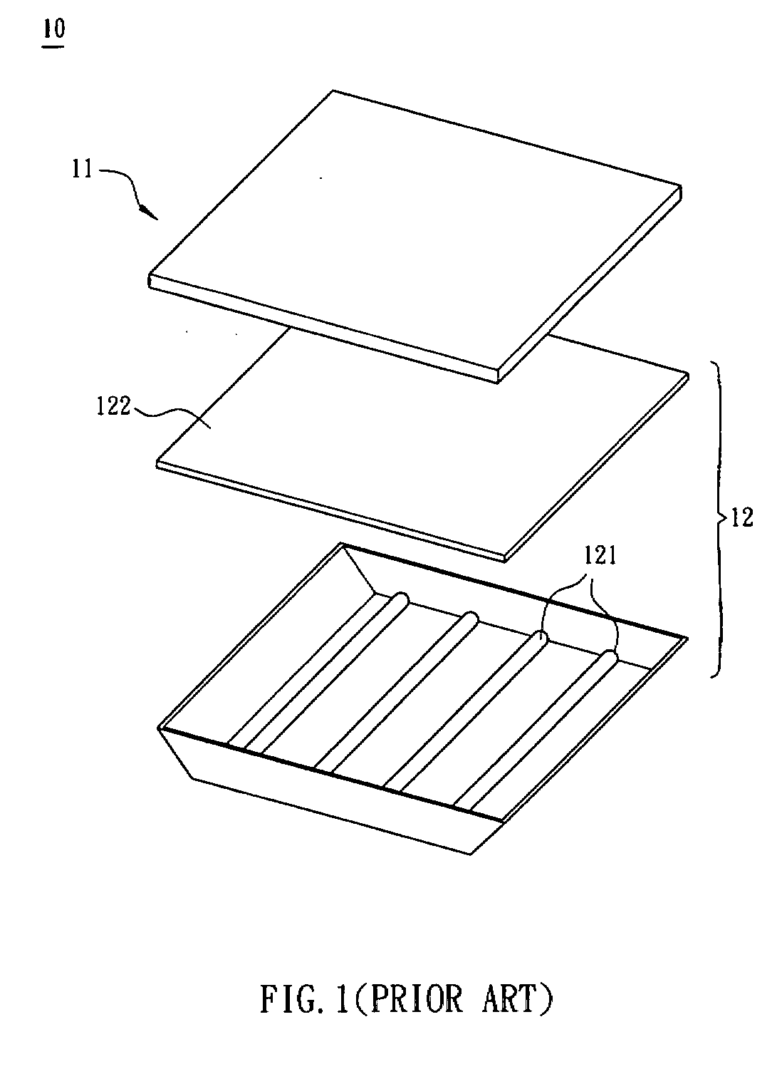
Despite the white balance problem, the conventional LCD display also has an image blur problem.
However, the backlight module is continuously turned on and off, so the brightness of the display varies, resulting in the flicker problem.

Method used


Image

  • Liquid crystal display apparatus and light emitting unit
  • Liquid crystal display apparatus and light emitting unit
  • Liquid crystal display apparatus and light emitting unit

Examples


first embodiment

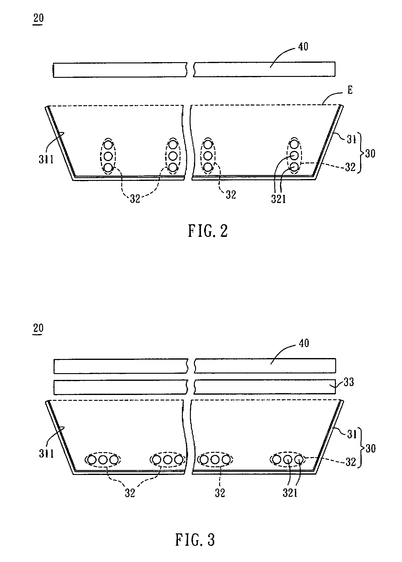
[0035]As shown in FIGS. 2 and 3, an LCD apparatus 20 includes a backlight module 30 and an LCD panel 40.

[0036]The backlight module 30 includes a back plate 31 and a plurality of lamp sets 32. The material of the back plate 31 is usually metal, so the back plate 31 can be made by pressing formation. In the embodiment, the back plate 31 has a reflective layer 311 to reflect the light emitted from the lamp sets 32 so as to increase the light usage. The reflective layer 311 is disposed opposite to the lamp sets 32. For example, the reflective layer 311 can be formed by attaching a reflective film on the back plate 31 or by coating a metal layer on the back plate 31.

[0037]The lamp sets 32 are disposed on the back plate 31. Each of the lamp sets 32 includes a plurality of lamps 321, which can emit lights of at least two colors. In the embodiment, the lamps 321 are CCFLs, and they can be linear lamps, U-shaped lamps or W-shaped lamps. As shown in FIG. 2, the lamps 321 are linear lamps. Eac...

second embodiment

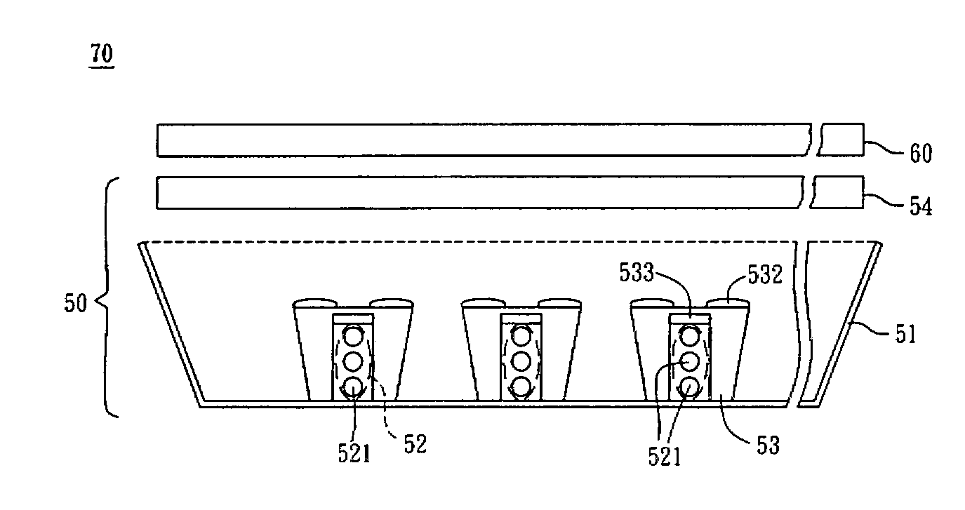
[0042]With reference to FIG. 4, the second embodiment is different from the first embodiment by that the back plate 31 of the backlight module 30 in the second embodiment is formed with a plurality of protrusions 312. For example, the protrusions 312 are spacers, and the lamp sets 32 are respectively disposed between the protrusions 312. Furthermore, the surface of each protrusion 312 can be formed with a reflective layer. By disposing the protrusions 312, the lights emitted from different lamp sets 32 are not interfered by each other, which is helpful for controlling the illumination and white balance of the lamp set 32 or controlling the sequential on / off of the lamp sets 32.

[0043]In the second embodiment, the backlight module 30 may further include a plurality of reflective covers 34 disposed corresponding to the lamp sets 32, respectively. The reflective covers 34 can be directly disposed over the lamp sets 32 to prevent the light from focusing at the place over the lamp sets 32...

third embodiment

[0045]With reference to FIG. 6, the third embodiment is different from the first embodiment by that the backlight module 30 of the LCD apparatus 20 further includes a plurality of light-guiding elements 35 disposed between the lamp sets 32. The light-guiding elements 35, which are made of optical resin such as polycarbonate (PC), can transmit the light emitted by the lamps 321 to the light-exit surface E. Each light-guiding element 35 includes a first light-guiding portion 351 and a second light-guiding portion 352. The shapes of the first light-guiding portion 351 and second light-guiding portion 352 are not limited. For example, the cross section of the first light-guiding portion 351 or the second light-guiding portion 352 can be trapezoid, triangular or other shape. In this embodiment, the cross section of the first light-guiding portion 351 and the second light-guiding portion 352 is trapezoid.

[0046]FIG. 7 is an enlarged view of the dot line portion shown in FIG. 6. FIGS. 8A to...


PUM

PropertyMeasurementUnit
colorsaaaaaaaaaa
red coloraaaaaaaaaa
blue coloraaaaaaaaaa

Abstract

A liquid crystal display apparatus includes a backlight module and a liquid crystal display panel. The backlight module includes a back plate and a plurality of lamp sets. The lamp sets are disposed on the back plate. Each of the lamp sets includes a plurality of lamps for emitting lights of at least two colors. The liquid crystal display panel is disposed adjacent to the backlight module. A light emitting unit is also disclosed.

Description

CROSS REFERENCE TO RELATED APPLICATIONS[0001]This Non-provisional application claims priority under 35 U.S.C. §119(a) on Patent Application Nos. 095127180 and 095127181 filed in Taiwan, Republic of China on Jul. 25, 2006, the entire contents of which are hereby incorporated by reference.BACKGROUND OF THE INVENTION[0002]1. Field of Invention[0003]The invention relates to a liquid crystal display apparatus and a light emitting unit, and, in particular, to a liquid crystal display apparatus and a light emitting unit having a plurality of lamps.[0004]2. Related Art[0005]Recently, various kinds of portable electronic devices have appeared in our lives, so the requirements for the display apparatuses with compact size and low power consumption that used in the electronic devices are increasing. The light crystal display (LCD) apparatus is one of the most popular display apparatuses due to its low power consumption, low heat generation, light and non-radiation properties. Moreover, the LCD...

Claims


Application Information

Patent Timeline
Patent Type & Authority Applications(United States)
IPC IPC(8): G02F1/13357F21S10/00
CPCF21V11/16G02F1/133621G02F1/133606G02F1/133605
Inventor LIN, FENG-LI
Owner GIGNO TECH CO LTD
Learn More