Mechanical assembly to support orthogonal airflow devices in a normal airflow slot of a server chassis

a technology of orthogonal airflow and server chassis, which is applied in the direction of electrical apparatus casings/cabinets/drawers, lighting and heating apparatus, and cooling/ventilation/heating modifications. it can solve the problems of large heat generation of computer systems, along with other components that support their use and maintenance, and limitations in how these components can be designed

Inactive Publication Date: 2008-01-31
IBM CORP
View PDF25 Cites 9 Cited by
  • Summary
  • Abstract
  • Description
  • Claims
  • Application Information

AI Technical Summary

Benefits of technology

[0013]It is preferred that the plurality of partitions includes a central partition extending between the modules to isolate the first airflow pathway under the second module from the second airflow pathway over the first module. It is also preferred that the housing includes a first air handling section to the left of one of the modules and a second air handling section to the right of one of the modules, wherein the first and second air handling sections are each divided into an inlet plenum and an exhaust plenum. The cross-sectional area of the inlet plenum may decrease from front to back and the cross-sectional area of the exhaust plenum may increase from front to back. Optionally, the inlet plenum does not extend the full length of the module. In a further option, the exhaust plenum does extend the full length of the module.

Problems solved by technology

Computer systems, along with other components that support their use and maintenance, generate large amounts of heat.
However, there are also limitations in how these components can be designed.
While some devices can be operated with airflow in either direction along a specific orientation, these devices are still not operable with airflow that is oriented at a right angle to the specified airflow.
For example, an orthogonal airflow device can not be used in a chassis that provides only normal airflow.
However, even these modules cannot operate in a slot where the airflow is from front-to-back.

Method used


Image

  • Mechanical assembly to support orthogonal airflow devices in a normal airflow slot of a server chassis
  • Mechanical assembly to support orthogonal airflow devices in a normal airflow slot of a server chassis
  • Mechanical assembly to support orthogonal airflow devices in a normal airflow slot of a server chassis

Examples


Embodiment Construction

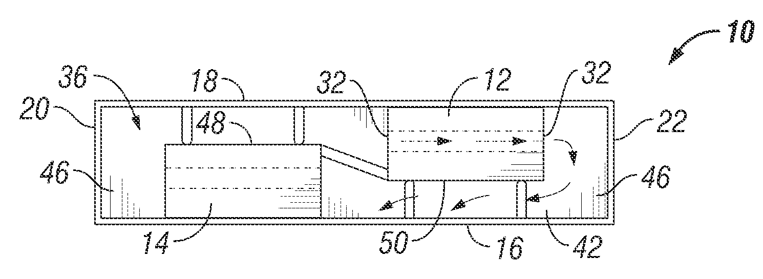
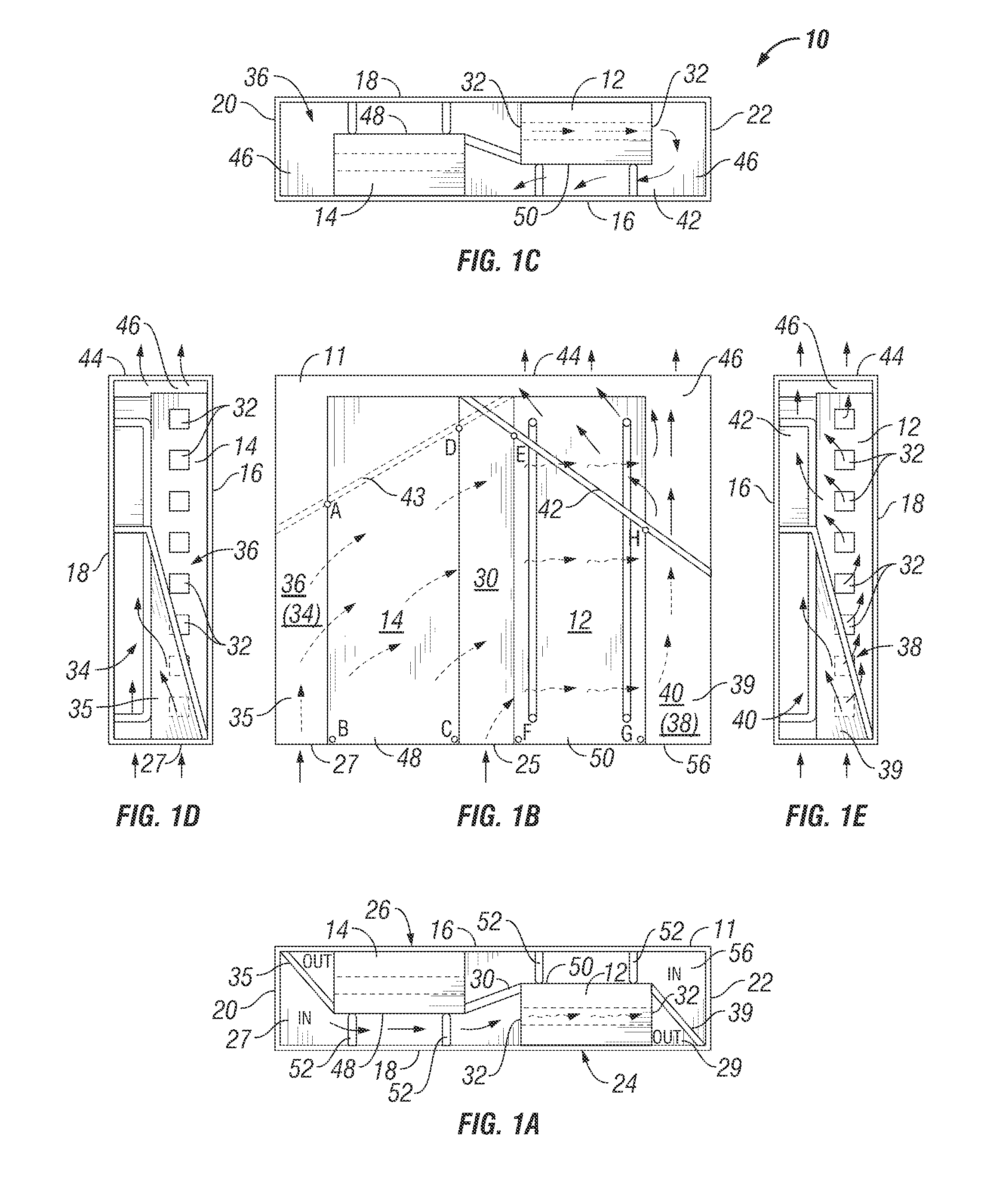
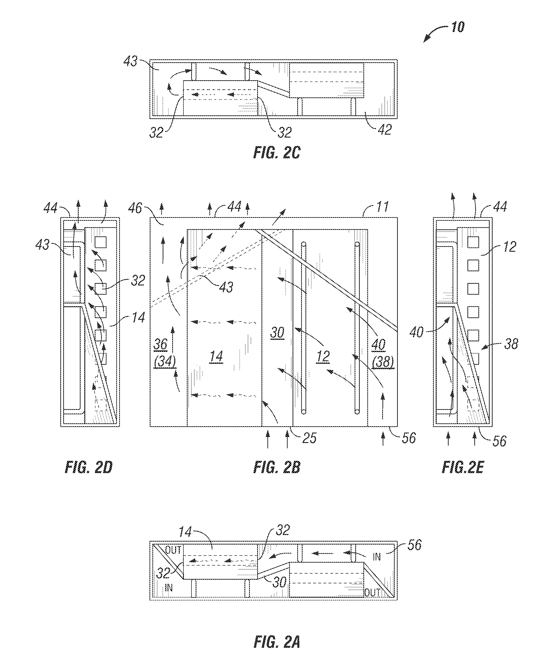
[0020]The present invention provides an apparatus or assembly that facilitates the use of modules requiring orthogonal airflow in a chassis providing normal airflow. The apparatus comprises a housing having a front face with an air inlet for drawing ambient air into the assembly for cooling the modules that have electronic components that generate heat during use. The housing also comprises a rear face having an air exhaust opposite the air inlet end for exhausting warmed air from the housing and thereby removing heat from the modules.

[0021]A plurality of partitions is disposed within the housing to direct airflow from the front air inlet, through the modules, and out the rear air exhaust. The housing and the plurality of partitions define first and second vertically and horizontally offset slots for receiving first and second orthogonal airflow modules. Preferably, the assembly is received in a slot designed for a pair of normal airflow devices. Accordingly, the assembly provides t...


PUM


Abstract

An assembly that facilitates the use of modules requiring orthogonal airflow in a chassis providing normal airflow. Partitions within the housing direct ambient airflow from the front air inlet, through the modules, and out the rear air exhaust. The housing and partitions define first and second vertically and horizontally offset slots for receiving first and second orthogonal airflow modules, and also define separate first and second airflow pathways. The first airflow pathway provides airflow through a front air inlet, under the second module, orthogonally through the first module and out the rear air exhaust. Similarly, the second airflow pathway provides airflow through a front air inlet, over the first module, orthogonally through the second module and out the rear air exhaust. Both airflow pathways both draw ambient air into the housing and exhaust warm air from the rear of the housing, while keeping the two airflow pathways separated.

Description

BACKGROUND OF THE INVENTION[0001]1. Field of the Invention[0002]The present invention relates to systems and methods for directing air flow through an electronics cabinet.[0003]2. Description of the Related Art[0004]Computer systems, along with other components that support their use and maintenance, generate large amounts of heat. This heat must be continually removed to prevent the components from reaching elevated temperatures that can cause damage or failure of the components. While heat sinks may be utilized to conduct heat away from a point source of heat and distribute that heat over a large surface area, it is air convection that is ultimately responsible for removing heat energy from the cabinet. In nearly all significant computer installations, the amount of heat that must be removed requires the use of forced convection through or around the heat producing component. The cabinets, chassis and individual components are designed and configured to accommodate the forced flow...

Claims


Application Information

Patent Timeline
Patent Type & Authority Applications(United States)
IPC IPC(8): H05K7/20
CPCH05K7/20581
Inventor HOLLAND, WILLIAM GAVIN
Owner IBM CORP
Why Eureka
Try Eureka