Specific Heat Measuring Method and Instrument

a technology of specific heat and measuring method, applied in the direction of instruments, specific gravity measurement, material heat development, etc., can solve the problems of large scale, long time to find, and high cost of instruments and personal expenses, and achieve the effect of reducing the cost of instruments and simple instrument configuration

Active Publication Date: 2008-01-31
KYOTO ELECTRON MFG CO LTD
View PDF13 Cites 6 Cited by
  • Summary
  • Abstract
  • Description
  • Claims
  • Application Information

AI Technical Summary

Benefits of technology

[0010] The present invention makes it possible to measure the specific heat of sample in a very simple manner. Since the specific heat can be measured by a very simple configurat

Problems solved by technology

However, there are disadvantages in the above-mentioned instrument; the configuration gets large scale; it takes a very lo

Method used


Image

  • Specific Heat Measuring Method and Instrument
  • Specific Heat Measuring Method and Instrument
  • Specific Heat Measuring Method and Instrument

Examples


Embodiment Construction

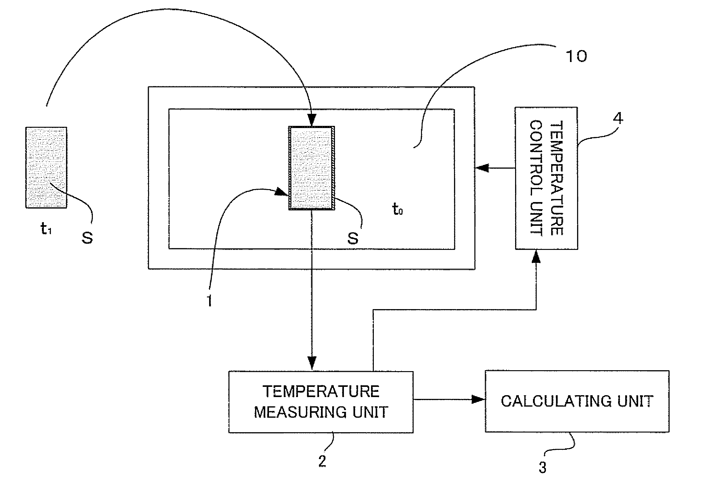
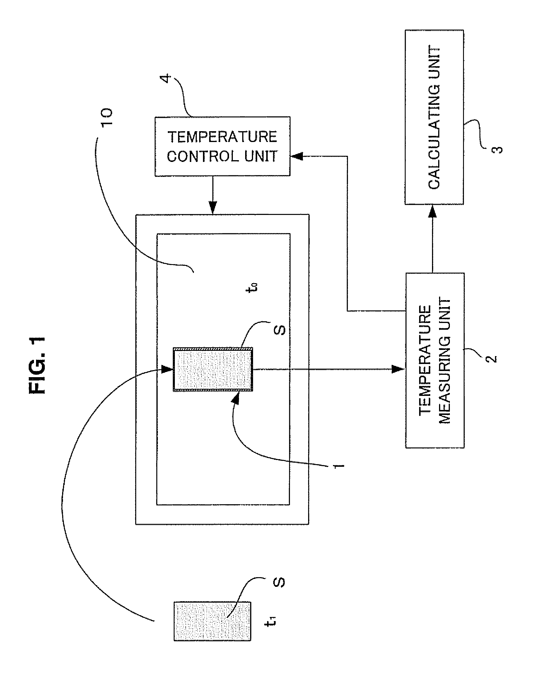
[0019]FIG. 1 is a diagram explaining a principle of the invention.

[0020] A predetermined amount of sample at a first temperature t1 is introduced in a measurement cell 1 of a measurement chamber 10, of which temperature is controlled to a second temperature t0 being different from the first temperature t1, and a change of the sample temperature is measured by a temperature measuring unit 2. With the assumption that a temperature control unit 4 keeps the temperature of the measurement chamber 10 at the above temperature t0, the temperature of the sample starts to vary (increase or decrease) to an endpoint temperature that is the second temperature t0, depending on the time constant. A calculating unit 3 calculates the time constant based on the change of the sample temperature obtained by the temperature measurement unit 2, and its result depends on a material of the sample.

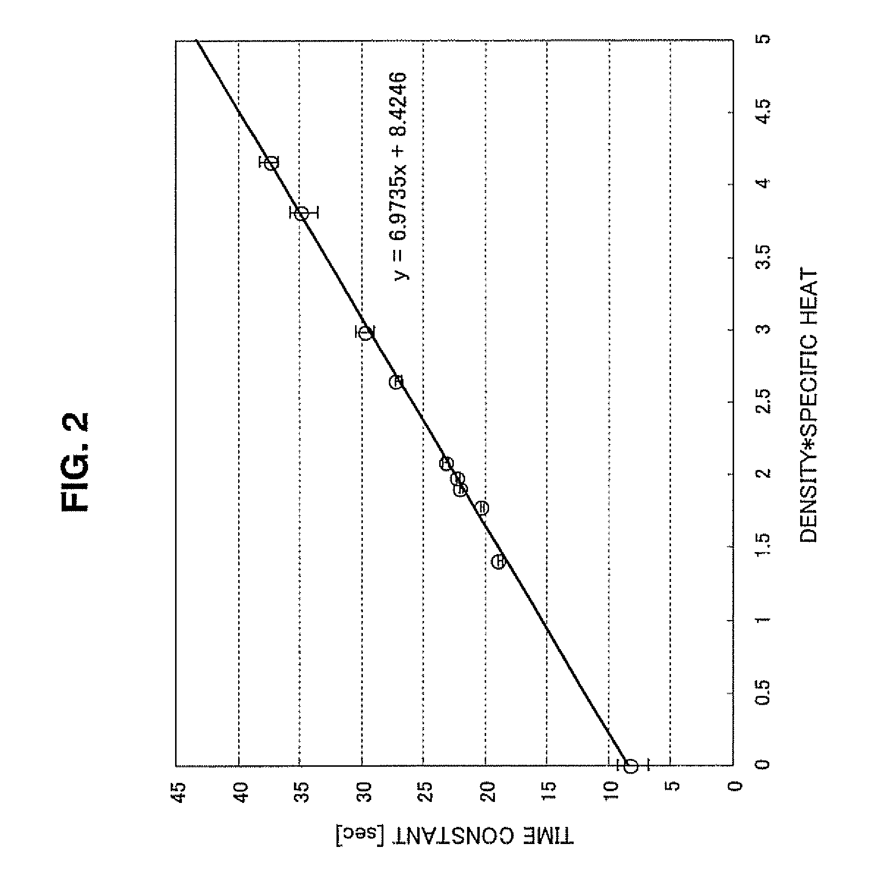
[0021] As a matter of course, it can be assumed that, in case of the same density of materials, the larger th...


PUM


Abstract

In order to measure specific heat, the measurement time is very long and the instrument is very expensive. The specific heat may be calculated based on the thermal time constant obtained from the change of the sample temperature when the predetermined amount of sample with known density at the first temperature is introduced in the environment at the second temperature. This measuring method can use the oscillatory densitometer. The predetermined amount corresponds to the volume of the sample to be introduced in the oscillatory densitometer, the density is a measurement result of the oscillatory densitometer, and the thermal time constant corresponds to the time constant of the oscillation period of the oscillatory densitometer.

Description

FIELD OF THE INVENTION [0001] This invention relates to a method of measuring specific heat and an instrument thereof, and more specifically relates to a specific heat measuring method and instrument using thermal time constant. DESCRIPTION OF THE RELATED ART [0002] The measurement of specific heat has been performed by a large-scale instrument. For instance, in a differential scanning calorimeter, a reference material r and a sample s are placed in holders 42r and 42s in an electric furnace 40, and a program temperature control means 45 heats the electric furnace so that the rate of the temperature increasing is kept at a constant, as shown in FIG. 8. The temperature difference between the sample s and the reference material r is detected by a temperature difference detecting means 43. In order to keep the temperature difference “0” a differential power compensation circuit 44 controls heaters 41r and 41s to heat the electric furnace. [0003] Under such configuration, the specific h...

Claims


Application Information

Patent Timeline
IPC IPC(8): G01K17/00G01N25/00G01N25/18
CPCG01N9/002G01N25/005G01N9/36
Inventor KAWAGUCHI, KENJIOBAYASHI, MASANOHUKURAUCHI, NAMI
Owner KYOTO ELECTRON MFG CO LTD
Why Eureka
Try Eureka