Methods, systems, and computer-program products to estimate scattered radiation in cone-beam computerized tomographic images and the like

a computerized tomographic and cone beam technology, applied in the field of tomography, can solve problems such as phantom images, electrical signals of surrounding pixel detectors, and slight non-uniform radiation distribution among circle perimeters, and achieve the effect of reducing image degradation and artifacts

Active Publication Date: 2008-01-31
VARIAN MEDICAL SYST INT AG +1
View PDF9 Cites 12 Cited by
  • Summary
  • Abstract
  • Description
  • Claims
  • Application Information

AI Technical Summary

Benefits of technology

[0011]It is yet another object of the several inventions of the present application to enable the reduction of image degradation and artifacts in images produced by cone-beam tomography systems and the like.

Problems solved by technology

However, the distribution of the radiation may be slightly non-uniform among the circle perimeters.
These scattered rays are often received by surrounding pixel detectors that are not located on the transmission path that the initial quantum of radiation was transmitted on, thereby creating errors in the electrical signals of the surrounding pixel detectors.
The scattered radiation causes artifacts (e.g., phantom images) and loss of resolution and contrast in the CT image slices produced by the radiation imaging system.
The scattered radiation can also cause numerical errors in the image reconstruction algorithms (generally referred to as “CT number problems” in the art).
The foregoing lead to image degradation.

Method used


Image

  • Methods, systems, and computer-program products to estimate scattered radiation in cone-beam computerized tomographic images and the like
  • Methods, systems, and computer-program products to estimate scattered radiation in cone-beam computerized tomographic images and the like
  • Methods, systems, and computer-program products to estimate scattered radiation in cone-beam computerized tomographic images and the like

Examples


Embodiment Construction

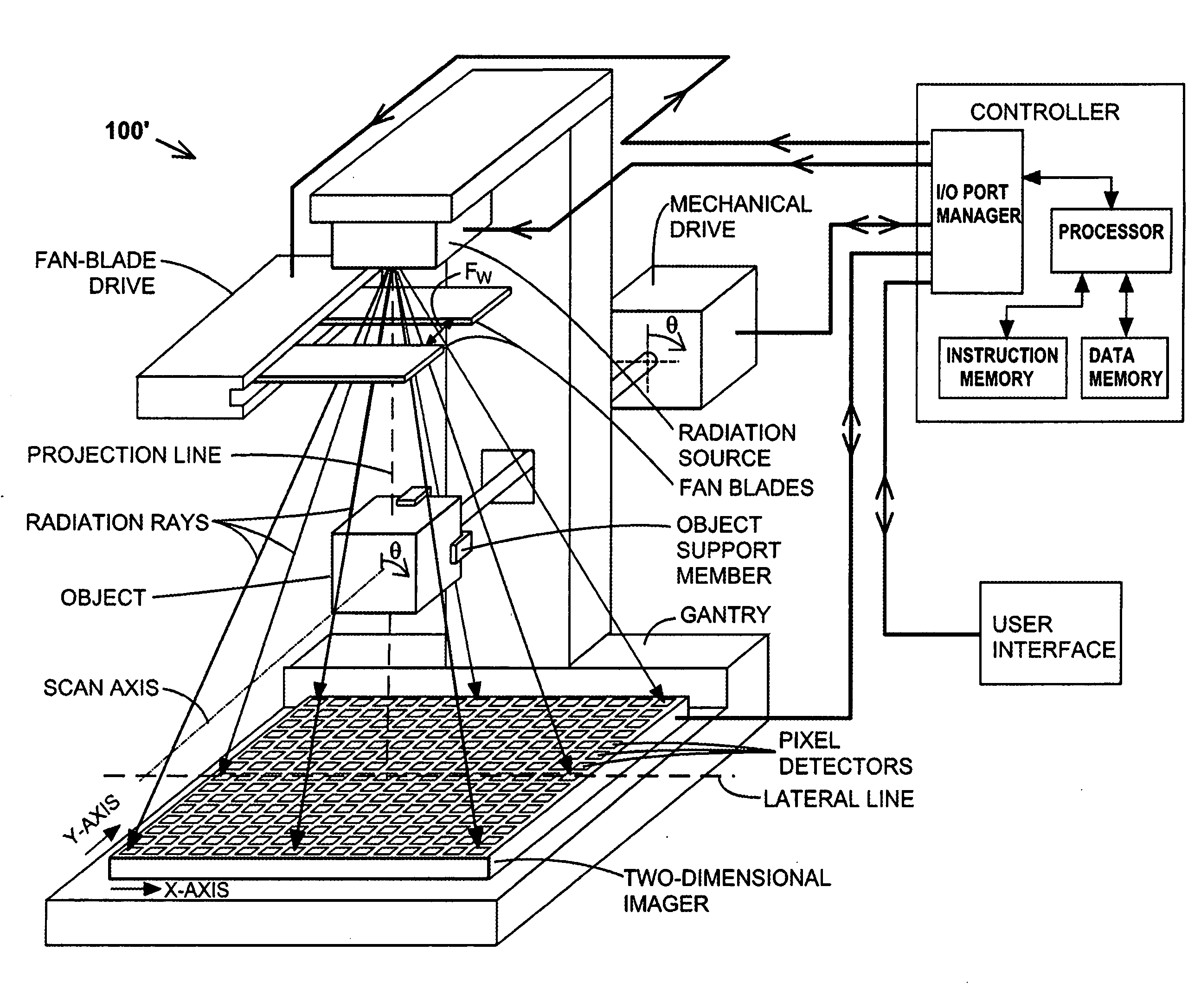
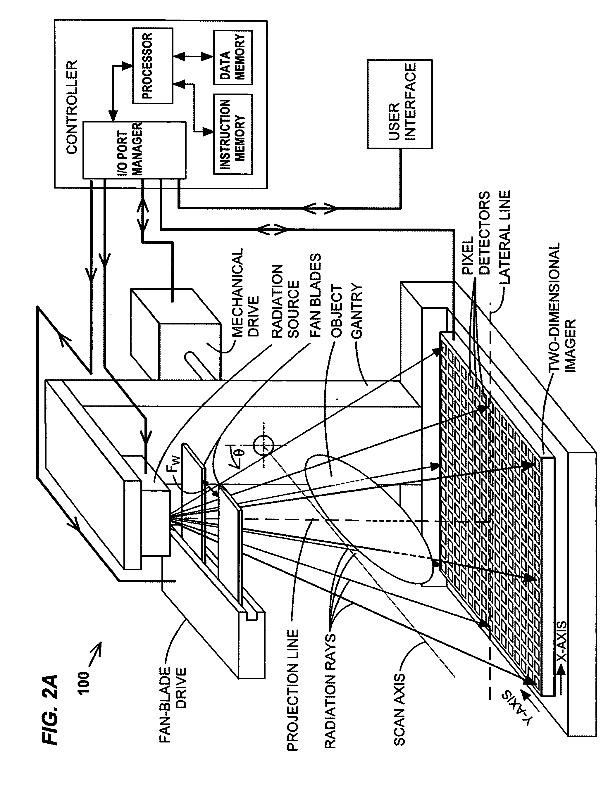
[0025]In the following description, numerous specific details are set forth to provide a more thorough description of specific embodiments of the present inventions. It is apparent, however, that the inventions may be practiced without all the specific details given below. In other instances, well known features have not been described in detail so as to not obscure the inventions. The following table of symbol nomenclature will provide a useful reference for the reader:[0026]R1—number of projections in a first group of radiographic projections;[0027]R2—number of projections in a second group of radiographic projections;[0028]r1—index for the radiographic projections of the first group, r1=1,2, . . . , R1;[0029]r2—index for the radiographic projections of the second group, r2=1,2, . . . , R2;[0030]θ—the angular displacement of the relative rotation between the projection line on the one hand and the scan axis and an object aligned thereto on the other hand, the angular displacement ...


PUM

PropertyMeasurementUnit
rotation anglesaaaaaaaaaa
angular displacementaaaaaaaaaa
spatial dimensionaaaaaaaaaa

Abstract

Disclosed are imaging systems, methods, and computer program products that generate estimates of scattered radiation in tomographic imaging systems, such as cone-beam computerized tomography (CBCT) systems, and the like. In an exemplary embodiment, a first group of projections is taken of an object with the radiation covering a wide band of the object, and a second group of projections is taken of the object with the radiation covering a narrower band of the object. The projections of the second group cover less of the object, but have less scattered radiation. The scattered radiation within the narrower band may be estimated from differences between projections from the first and second groups, or from representations thereof.

Description

FIELD OF THE INVENTION[0001]The present invention relates to tomography, and more particularly to correcting errors caused by extraneous radiation in tomographic systems, such as cone-beam computerized tomography (CBCT) systems, and the like.BACKGROUND OF THE INVENTION[0002]Cone-beam tomography (CT) involves the imaging of the internal structure of an object by collecting several projection images (“projections”) in a single scan operation (“scan”), and is widely used in the medical field to view the internal structure of selected portions of the human body. Typically, several two-dimensional projections are made of the object, and a three-dimensional representation of the object is constructed from the projections using various tomographic reconstruction methods. From the three-dimensional image, conventional CT slices (e.g., cross-sections) through the object can be generated. The two-dimensional projections are typically created by transmitting radiation from a “point source” thr...

Claims


Application Information

Patent Timeline
Patent Type & Authority Applications(United States)
IPC IPC(8): A61B6/00G01D18/00G01N23/00G21K1/12H05G1/60
CPCA61B6/032A61B6/06G06T11/005A61B6/583A61B6/5205A61B6/5282Y10S378/901
Inventor VIRSHUP, GARYSURI, ROLANDSEPPI, EDWARDSHAPIRO, EDWARDSTAR-LACK, JOSHCHELL, ERIK WILLIAM
Owner VARIAN MEDICAL SYST INT AG
Why Eureka
Try Eureka