Powder conveying apparatus

a conveying apparatus and conveying technology, applied in the direction of electrographic process apparatus, instruments, optics, etc., can solve the problems of requiring a higher reducing the conveying speed of the developer, and consuming a lot of developer containing toner, so as to achieve the effect of not reducing the conveying speed

Active Publication Date: 2008-01-31
KYOCERA DOCUMENT SOLUTIONS INC
View PDF6 Cites 27 Cited by
  • Summary
  • Abstract
  • Description
  • Claims
  • Application Information

AI Technical Summary

Benefits of technology

[0007]An object of the present invention is to provide a powder conveying apparatus which enables sufficient agitation of powder such as developer without reducing the conveying speed.

Problems solved by technology

However, such a configuration containing a rib causes a problem that the powder conveying speed became lower than that when the rib is absent.
Higher printing speed leads to higher consumption rate of the developer containing toner, which, in turn, demands higher conveying speed of the developer.
On the other hand, the increase in conveying speed causes a problem of insufficient agitation of the developer.

Method used


Image

  • Powder conveying apparatus
  • Powder conveying apparatus
  • Powder conveying apparatus

Examples


first embodiment

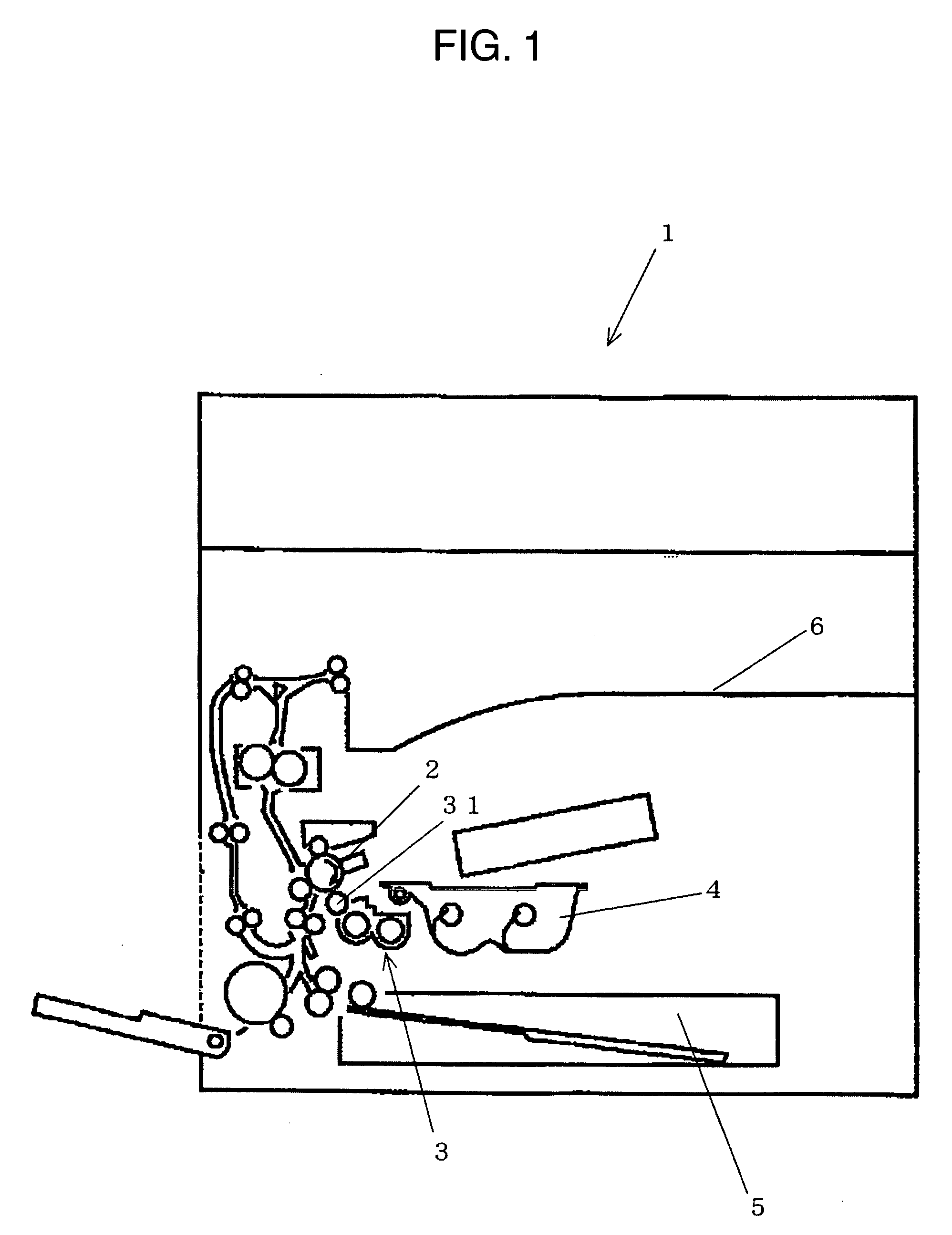
[0020]FIG. 1 is a schematic diagram illustrating an image forming apparatus 1 provided with a developing device or powder conveying apparatus having a powder agitating / conveying member according to an embodiment of the present invention. The image forming apparatus 1 has a photoconductive drum 2 for transferring a print image on a conveyed image bearing medium such as a sheet of paper, a developing device 3 provided with a developing roller 31 for developing a latent image formed on the photoconductive drum 2, a toner cartridge 4 for supplying toner to the developing device 3, a sheet supply tray 5 for supplying transfer sheet, and a sheet discharge tray 6 to which a transfer sheet bearing a print image is discharged. The present invention is applicable widely, for example, to laser printer, facsimile, and copying machine that use a developer such as toner.

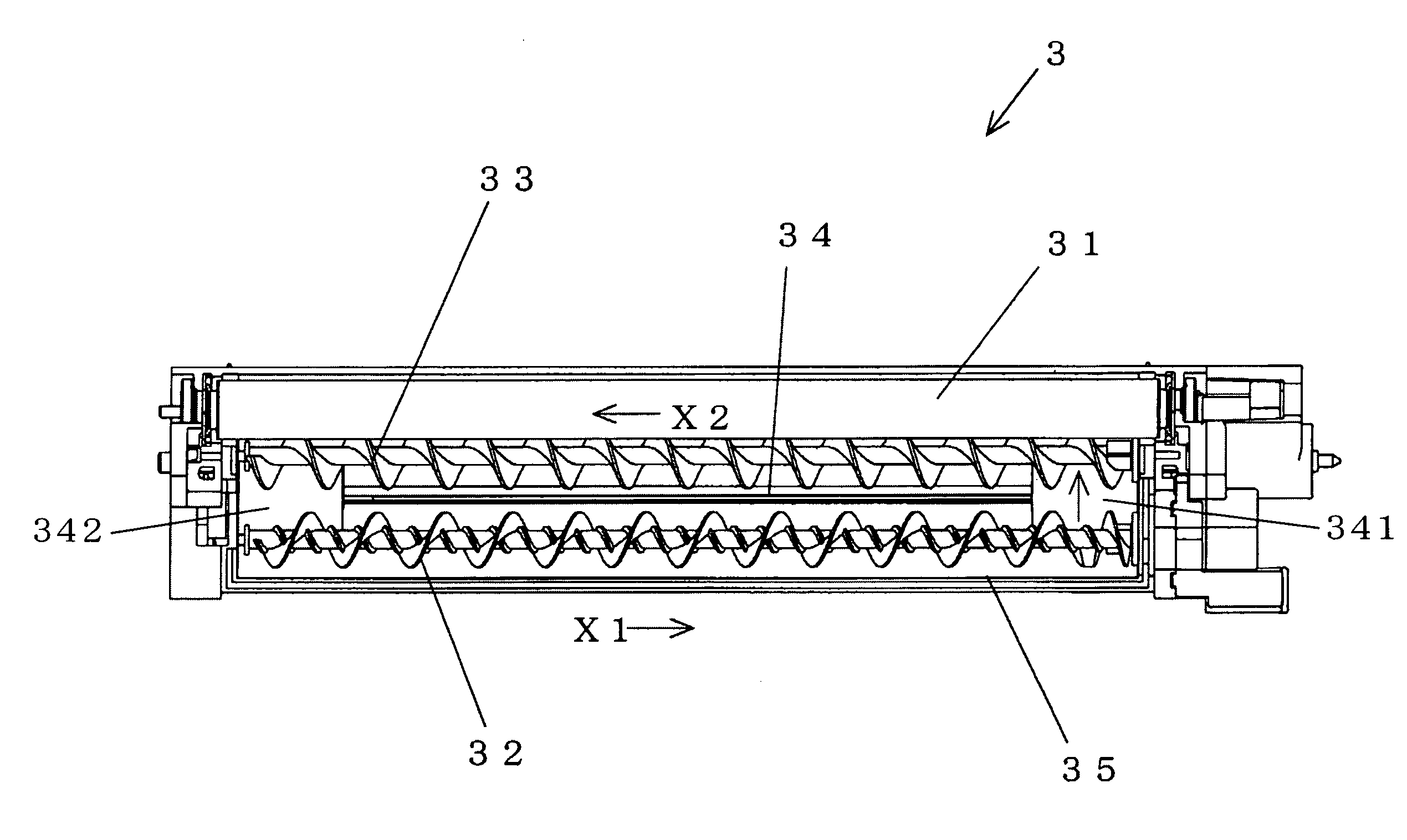
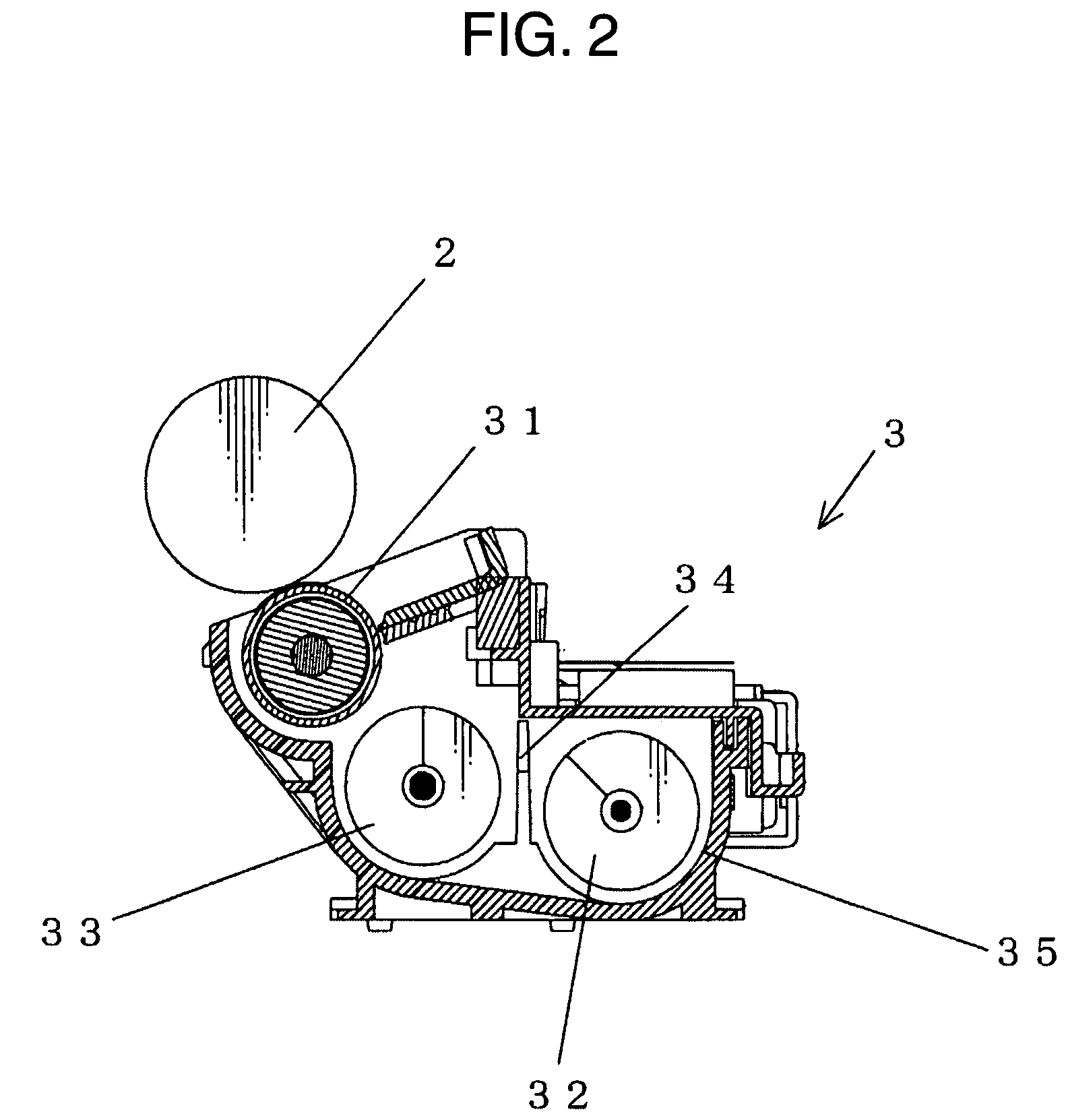
[0021]FIG. 2 is a sectional view illustrating the developing device shown in FIG. 1. FIG. 3 is a top plan view illustrating the ...

second embodiment

[0043]A powder agitating / conveying member according to another embodiment of the present invention will be described. The powder agitating / conveying member described below may be used, replacing the upstream powder agitating / conveying member 32 (as needed, downstream powder agitating / conveying member 33) described in the embodiment above.

[0044]FIGS. 6A and 6B are diagrams showing conveying forces of the powder agitating / conveying member in the second embodiment. FIG. 6A shows an entirety, and FIG. 6B shows an expanded part the powder agitating / conveying member shown in FIG. 6A. In the present embodiment, a powder agitating / conveying member 32b is placed in a powder container 35 for storing developer containing toner particles, and has a shaft 321 revolving around an axis thereof, a first screw blade 322 (primary conveying blade), and a second screw blade 323′ (secondary conveying element).

[0045]The first screw blade 322 is formed on an external surface of the shaft 321 to thereby co...

third embodiment

[0052]The secondary conveying element, i.e., second screw blades 323 and 323 in the foregoing two embodiments, may be replaced with a groove formed spirally in an external surface of the shaft 321. FIGS. 7A to 7C are diagrams showing conveying forces of a powder agitating / conveying member in the third embodiment of the present invention. FIG. 7A shows an entirety; FIG. 7B shows an expanded part of the power agitating / conveying member shown in FIG. 7A; and FIG. 7C shows a further expanded part of the part shown in FIG. 7B.

[0053]As shown in FIG. 7A, a groove is formed spirally in the external surface of the shaft 321 in a pitch space P1 of the first screw blade 322 of the powder agitating / conveying member 32c in the third embodiment. The groove 324 generates a conveying force b, similarly to the second screw blade 323 in the first embodiment.

[0054]More specifically, the first screw blade 322 applies, to the developer, a conveying force A of conveying the developer containing toner par...


PUM

PropertyMeasurementUnit
diameteraaaaaaaaaa
diameteraaaaaaaaaa
conveying forceaaaaaaaaaa

Abstract

A powder conveying apparatus, comprising a powder container for storing powder and a powder agitating / conveying member provided in the powder container, wherein the powder agitating / conveying member includes: a shaft revolving around the axis; a primary conveying blade provided on the external surface of the shaft in such a manner that the powder is conveyed in the first direction toward one side of the axial direction, by revolution in one rotational direction around the axis of the shaft; and a secondary conveying element provided on the external surface of the shaft and located radially inner than a radially outer end of the primary conveying blade in the diameter direction in such a manner that conveying force is applied to part of the powder, which is conveyed in the first direction by the primary conveying blade, in the second direction toward the other side of the axial direction.

Description

BACKGROUND OF THE INVENTION[0001]1. Field of the Invention[0002]The present invention relates to a powder conveying apparatus conveying while agitating powder such as developer.[0003]2. Description of the Background Art[0004]Image forming apparatuses, such as copying machine, printer and facsimile, forming an image by using developer containing toner particles have a developing device for conveying powder such as developer containing toner while stirring it. Such a developing device has a powder agitating / conveying member conveying while agitating powder. The powder agitating / conveying member has a screw blade connected to a shaft that agitates and conveys the powder by revolution around an axis thereof.[0005]For prevention of toner scattering and image defects such as high background soil by thorough agitation of the powder, known is a configuration having, between screw blades, a rib inclined toward revolution direction from an external surface to a center of the shaft and also in...

Claims


Application Information

Patent Timeline
Patent Type & Authority Applications(United States)
IPC IPC(8): G03G15/08
CPCG03G2215/0827G03G15/0877G03G15/0893
Inventor SUENAMI, KOJI
Owner KYOCERA DOCUMENT SOLUTIONS INC
Why Eureka
Try Eureka