Angular Velocity Calculating Device, Offset Determination Method for the Same, and Vehicle Stopping Detecting Device

a technology of angular velocity calculating and offset determination, which is applied in vehicle testing, structural/machine measurement, instruments, etc., can solve the problems of inaccurate offset value, inability to prevent, and inability to accurately measure offset value, so as to prevent the update of offset and detect the effect of accurate offset value and accurate offset valu

Active Publication Date: 2008-01-31
ALPINE ELECTRONICS INC
View PDF8 Cites 17 Cited by
  • Summary
  • Abstract
  • Description
  • Claims
  • Application Information

AI Technical Summary

Benefits of technology

[0012]Accordingly, it is an object of the present invention to prevent a wrong offset value from being fetched when a vehicle employing a vehicle speed sensor having an insensible zone at a low-speed area travels at a low speed. It is another object of the present invention to prevent a wrong offset value from being fetched when a vehicle is turning on a turntable. It is still another object of the present invention to accurately detect stopping and starting of movement of a vehicle using a gyro output signal even when the vehicle is not equipped with a vehicle speed sensor, and to calculate an accurate offset value.
[0032]According to one aspect of the present invention, the minimum and maximum values of the angular velocity signals output when the vehicle is stationary are detected. The range of the angular velocity signal to determine whether the vehicle is considered to be stationary is set. When the angular velocity signal output from the gyro exceeds the range, the vehicle is determined to start moving. The average angular velocity signal having been calculated and stored a set time before the movement start detection time is output as the offset value. Thus, even when the vehicle does not have the vehicle speed sensor, the stopping and starting of movement of the vehicle can be accurately detected using the gyro output signal and the accurate offset value can be output.
[0033]According to one aspect of the present invention, if the variation of the average angular velocity is within the set range, the vehicle is stationary, and the difference between the currently fetched offset value fetched and a previously fetched offset value is within the allowable range, the average angular velocity is calculated and determined as the offset value. Thus, when the vehicle employing the vehicle speed sensor having the insensible zone at the low speed area travels at a low speed, update of the offset is prevented because the difference exceeds the allowable range. In addition, while the vehicle is turning on a turntable, the update of the offset is prevented because the difference exceeds the allowable range. Accordingly, it is possible to prevent the wrong offset value from being fetched.

Problems solved by technology

However, there are cases where an offset value cannot be accurately measured when a vehicle is stationary such as when a vehicle starts to move while a steering wheel is turned.
However, in the second known method, a wrong offset value may be undesirably fetched when the vehicle travels at a low speed, or fetching of a wrong offset value while a turntable on which the vehicle is placed is turning cannot be prevented.
However, in a vehicle using a vehicle speed sensor having an insensible zone at a low-speed area, the vehicle speed sensor does not generate vehicle speed pulses when the vehicle travels at a low speed of 1 to 2 km / h.
For this reason, since the angular velocity calculating device performs measurement of the direction of the vehicle using the wrong offset value while the vehicle is traveling, accurate direction measurement cannot be made.
In such a case, it is impossible to accurately measure the direction using the second known technique.
In addition, in a parking lot equipped with a turntable, since angular velocity is stabilized at a constant level for several seconds, if a turntable smoothly turns as shown in FIG. 15, an angular velocity calculating device determines that a vehicle is in a stationary state and calculates a wrong offset value, which prevents the accurate measurement of the direction.
Thus, the second known technique cannot be applied to vehicles not equipped with vehicle speed sensors, and vehicles equipped with vehicle speed sensors may not generate vehicle speed pulses at a low speeds.
There are many vehicles made in Europe incapable of physically deriving vehicle speed pulses.
Further, there are vehicles incapable of detecting vehicle speed pulses if the vehicles travel at a low speed of 4 to 5 km / h.
However, in a third known technique, it is impossible to accurately detect the stopping and starting of movement of the vehicle and to obtain an accurate offset value, reasons of which will be described below.
However, in such a stationary range setting method, a start of movement of a vehicle cannot be detected accurately, and a wrong offset A or B is fetched when the vehicle is slightly turning at the time the vehicle starts to move.
As a result, a measurement error of the vehicle direction is caused during movement, and a mismatch is caused in map matching of the navigation control or a circumstance in which a vehicle mark is deviated from a road occurs.

Method used


Image

  • Angular Velocity Calculating Device, Offset Determination Method for the Same, and Vehicle Stopping Detecting Device
  • Angular Velocity Calculating Device, Offset Determination Method for the Same, and Vehicle Stopping Detecting Device
  • Angular Velocity Calculating Device, Offset Determination Method for the Same, and Vehicle Stopping Detecting Device

Examples


first embodiment

(A) First Embodiment

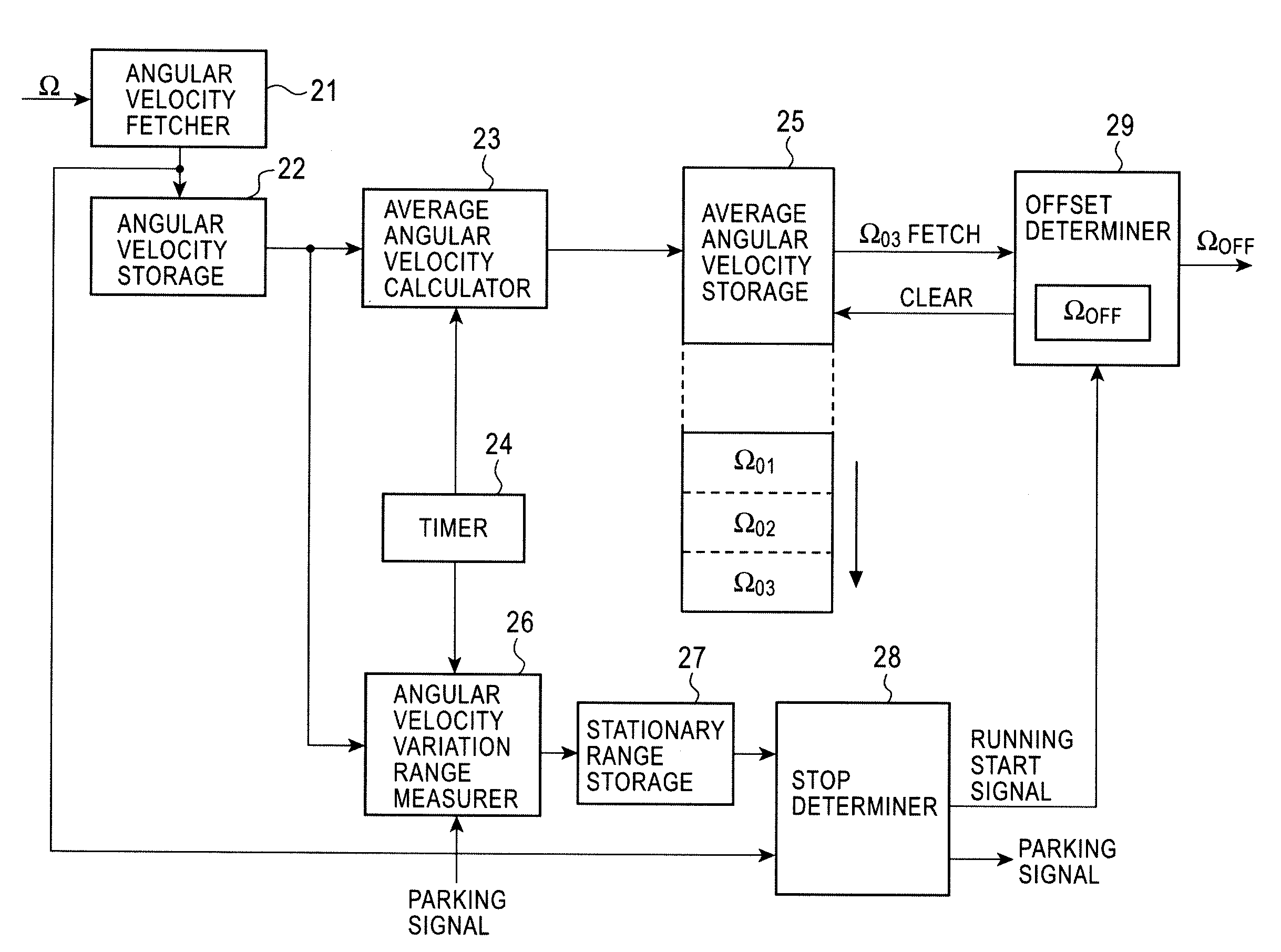
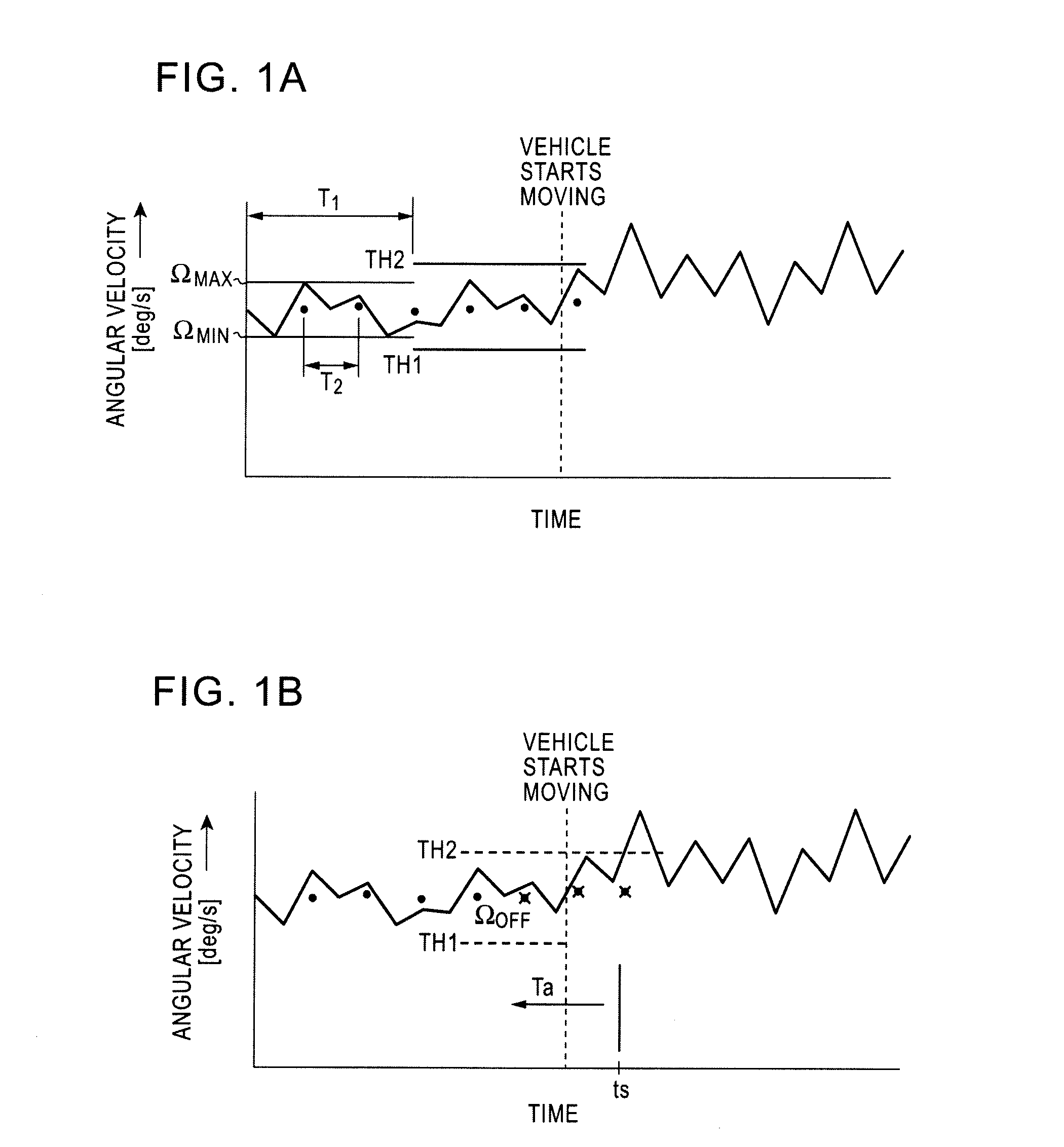
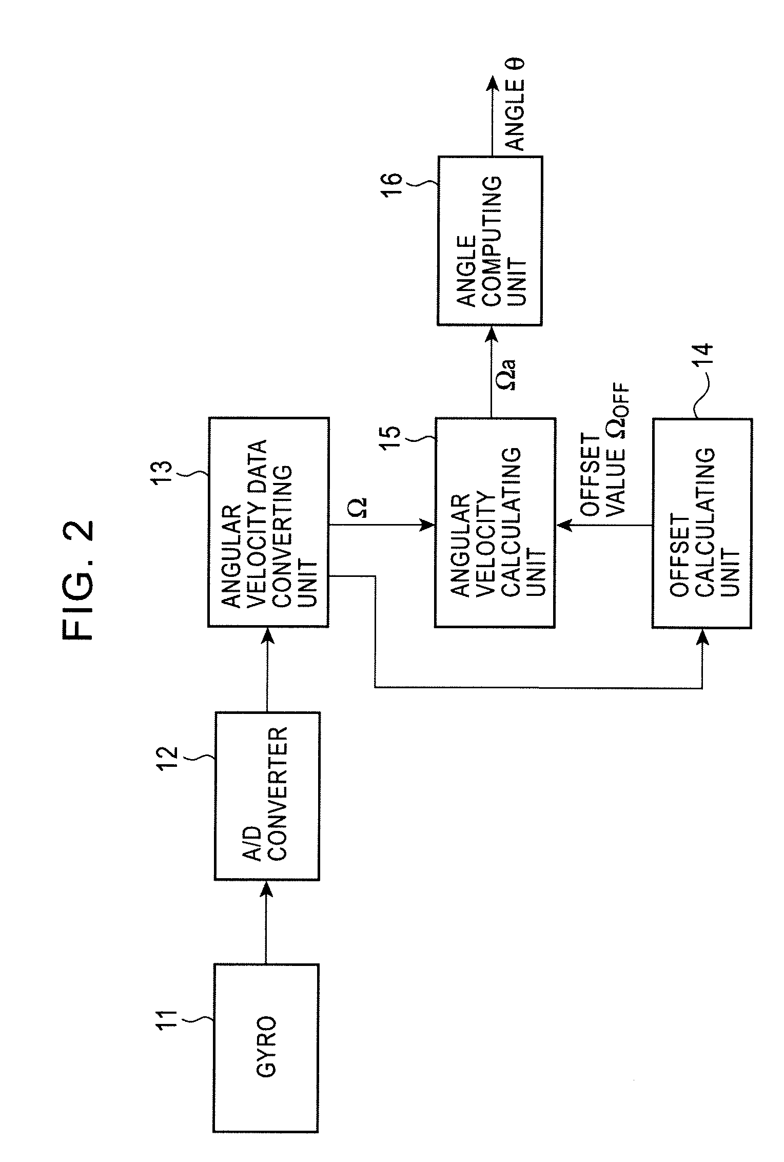
[0051]FIGS. 1A and 1B are diagrams illustrating angular velocity versus time. FIGS. 1A and 1B show an embodiment where a vehicle does not have a vehicle speed sensor. As shown in FIG. 1A, when a vehicle is stationary, a minimum value ΩMIN and a maximum value ΩMAX of an angular velocity signal output from a gyro during a predetermined period T1 (e.g., three seconds) are detected to determine thresholds TH1 and TH2 of a range of the angular velocity signal which is used to determine whether the vehicle is considered to be stationary. Suppose that the threshold TH1 is set to a value equivalent to a value 20 percent less of the minimum value ΩMIN, while the threshold TH2 is set to a value equivalent to a value 20 percent more of the maximum value ΩMAX in consideration of a margin. A range between thresholds TH1 and TH2 is employed as a range of the angular velocity signal used to determine whether the vehicle is considered to be stationary. Along with this, an averag...

second embodiment

(B) Second Embodiment

[0061]A second embodiment assumes an embodiment where a vehicle has a vehicle speed sensor. In the second embodiment, a vehicle is determined to be stationary if a vehicle pulse is not generated from the vehicle speed sensor for at least a predetermined period (e.g., 1.2 seconds).

[0062]In the second embodiment, whether or not the vehicle is stationary is determined based on the vehicle speed pulse generated by a vehicle speed sensor 51. If a variation of average angular velocity is within a set range, the vehicle is stationary, and a difference from an offset value fetched last time is within an allowable range, the latest average angular velocity is adopted as an offset value.

[0063]FIG. 7 is a diagram illustrating a configuration of an angular velocity calculating device according to the second embodiment. The same units as those described in the first embodiment shown in FIG. 2 are denoted by the same numerals. The second embodiment differs from the first embo...


PUM


Abstract

Minimum and maximum values of an angular velocity signal output from a gyro while a vehicle is stationary are detected. A range of the angular velocity signal is set that is used to determine when the vehicle is stationary. When the angular velocity signal output from the gyro exceeds the range, the vehicle starts to move, offset values calculated within a set time from a movement start detection time are discarded, and an average angular velocity signal having been calculated and stored the set time before, is output as the offset value. Thus, even when the vehicle does not have a vehicle speed sensor, the stopping and starting of the movement of the vehicle can be accurately detected using the output signal from the gyro and the accurate offset value can be output.

Description

RELATED APPLICATIONS[0001]The present application claims priority to Japanese Patent Application Serial Number 2006-207619, filed Jul. 31, 2006, the entirety of which is hereby incorporated by reference.BACKGROUND OF THE INVENTION[0002]1. Field of the Invention[0003]The present invention relates to angular velocity calculating devices, offset determination methods for the same, and vehicle stopping detecting devices. In particular, the present invention relates to an angular velocity calculating device, an offset determination method for the same, and a vehicle stopping detecting device for averaging angular velocity signals output from a gyroscope (gyro) while a vehicle is stationary to calculate an offset value, and canceling the offset value from an angular velocity signal output while the vehicle is moving to output angular velocity.[0004]2. Description of the Related Art[0005]Angular velocity calculating devices for calculating a rotation angle of a vehicle using signals corres...

Claims


Application Information

Patent Timeline
Patent Type & Authority Applications(United States)
IPC IPC(8): G01M17/06G01C19/00
CPCG01C19/42B60W2520/14
Inventor SEWAKI, KOJI
Owner ALPINE ELECTRONICS INC
Why Eureka
Try Eureka