Urinal cartridge with improved performance

a technology of urinal cartridges and urinals, applied in water installations, construction, domestic applications, etc., can solve the problems of reducing the life of the cartridge, relating to the loss of sealant,

Inactive Publication Date: 2008-02-07
FALCON WATERLESS TECH INC
View PDF12 Cites 25 Cited by
  • Summary
  • Abstract
  • Description
  • Claims
  • Application Information

AI Technical Summary

Benefits of technology

[0004] These and other problems are successfully addressed and overcome by the present invention by including at least one reservoir, a primary reservoir, within the cartridge; if desired, a secondary sealant reservoir may be used. The primary reservoir provides an immediate supply of sealant to the wastewater-inlet or receiving chamber. The secondary reservoir forms an overflow source which is minimally affected by pressure differentials and turbulence exerted on the wastewater-receiving chamber due to excessive fluid flow, such as through the dumping of water into the cartridge. As an added potential guard against loss of sealant, the wastewater-receiving chamber is configured with a minimum area, a throat, where the sealant is floated on the wastewater. Further, the wastewater outlet-to-drain compartment is sufficiently large as to prevent siphoning of liquid within the cartridge should a negative pressure differential exist across the cartridge trap or should their be any excessive amount of fluid dumped into the cartridge. The cartridge acts as a trap for blocking sewer gases and / or wastewater odors from fouling the restroom.
[0005] Several advantages are derived from this arrangement. Sealant loss is minimized; conversely, sealant use is maximized. Siphoning of liquid from the cartridge, such as resulting from excessive fluid flow into the cartridge is guarded against. Cartridge useful life is extended.

Problems solved by technology

Moreover, problems arose relating to the loss of sealant such as occasioned by the dumping of water into the cartridge which would flush the sealant into the drain.
Repeated loss of the sealant would significantly reduce the life usage of the cartridge.

Method used


Image

  • Urinal cartridge with improved performance
  • Urinal cartridge with improved performance
  • Urinal cartridge with improved performance

Examples


Embodiment Construction

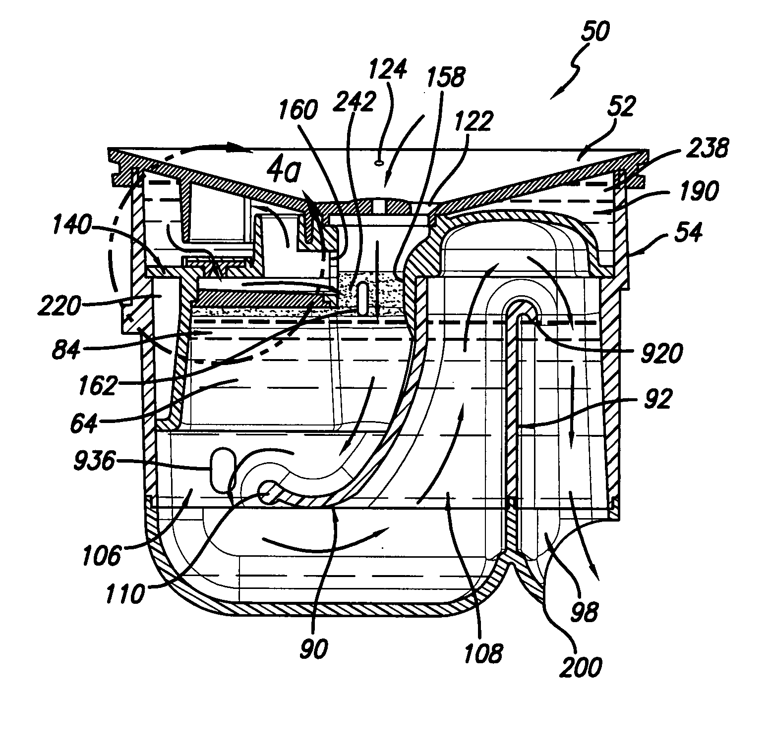
[0074] In the following exposition, a first embodiment has openings to a secondary reservoir or chamber for holding sealant and any wastewater that may accompany it. The second embodiment has a modification of the first embodiment in which such openings are not employed and, therefore, do not utilize the secondary reservoir or chamber. The third embodiment utilizes a water reservoir. Consistent therewith, the figure numbering and indicia attendant to the components depicted in the figures relevant to the second embodiment modification use numerals and the letter “M” and, for the third embodiment, indicia using the letter “x”; otherwise, there are no other distinguishing features made among the three embodiments. The three preferred embodiments can be used individually or in combination

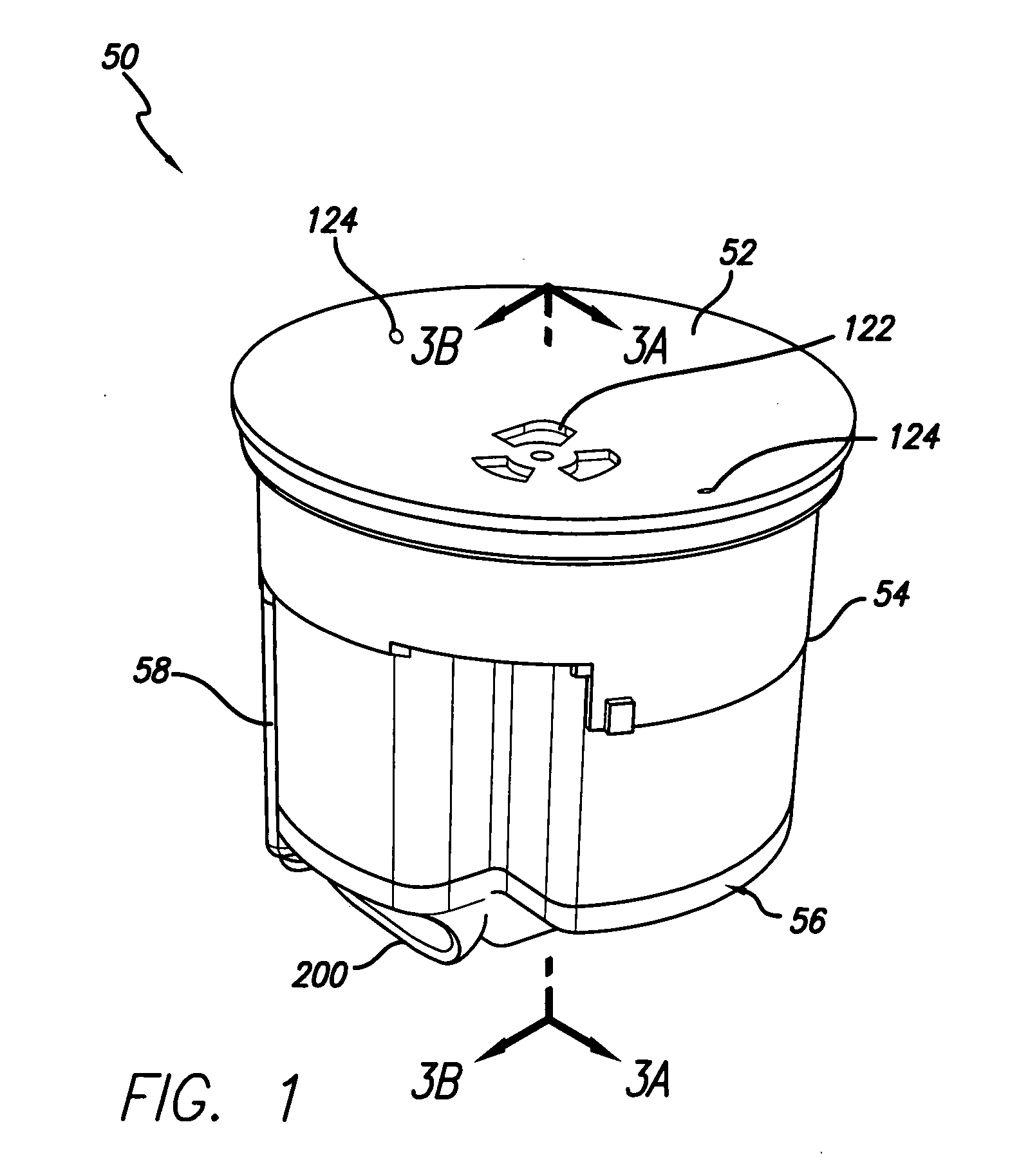
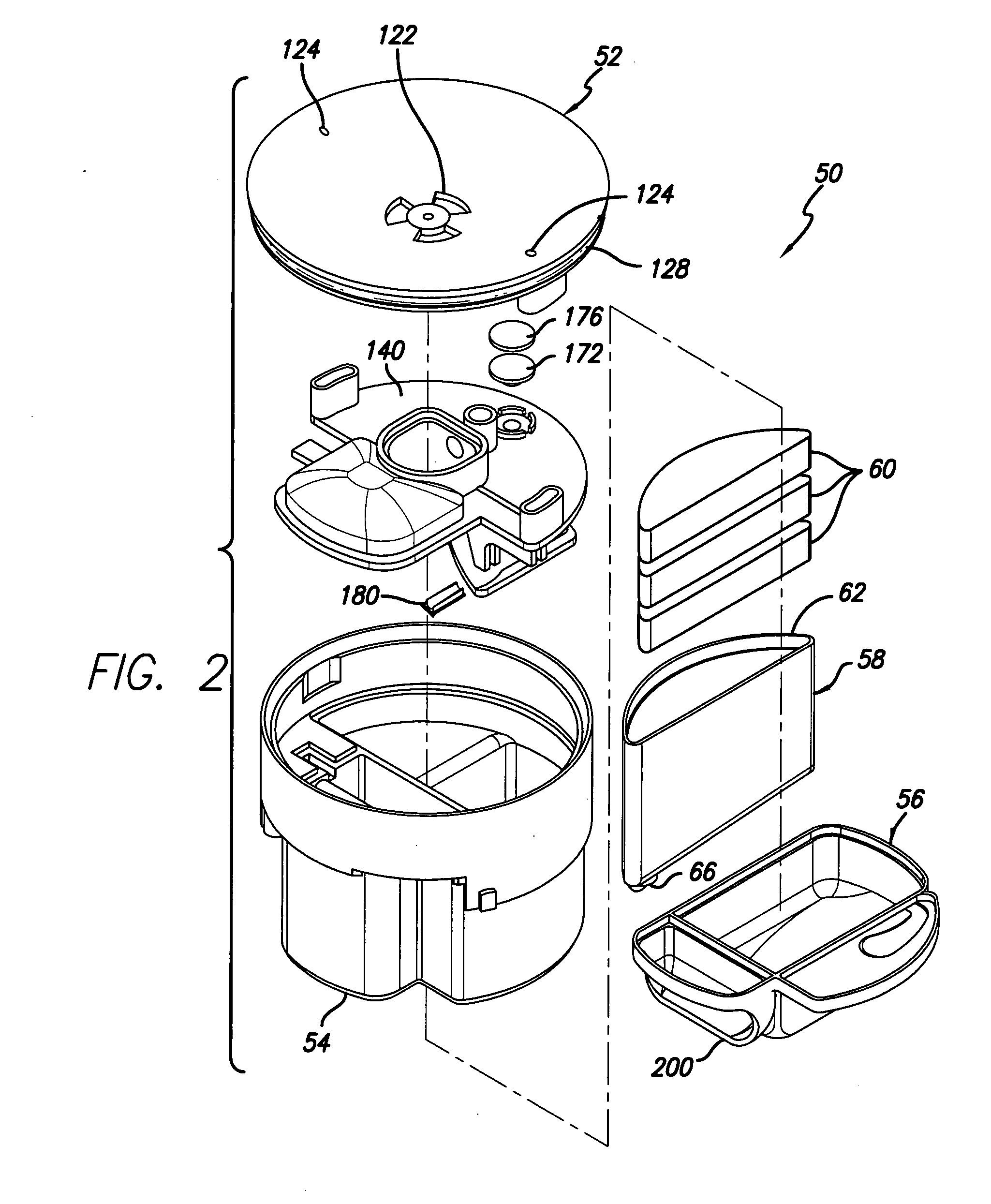
[0075] Accordingly, as shown in FIGS. 1-4, 4A and 4M, a cartridge 50 for placement in a urinal includes a top portion 52, an intermediate portion 54 / 54M and a bottom portion 56. A compartment 58, cont...


PUM


Abstract

A cartridge for placement in a urinal includes a chamber having an entry for receiving wastewater (e.g., urine), a quantity of sealant floatable on the wastewater in the chamber for functioning as a barrier to odors that may otherwise emanate from the wastewater in the chamber, a sealant reservoir coupled to the chamber for containing a supply of the sealant, and a closed path sealant dispenser for dispensing the sealant from the sealant reservoir to the chamber for maintaining the sealant modicum atop the wastewater. The sealant dispenser includes a cap having a U-shaped channel, and opening, and an orifice entering into a throat in which the sealant floats. An air vent avoids the buildup of suction in the primary reservoir. A secondary reservoir may be coupled to the sealant reservoir primarily for retaining additional sealant, in addition to any wastewater that might accompany the sealant for conserving sealant, and is particularly useful to avoid the deleterious effects of water being dumped into cartridge, particularly, sealant that is flushed out and into drain through the outlet-to-drain compartment, which flushing has a minimal effect on the sealant in the secondary reservoir. If desired, a water reservoir may be housed within the cartridge.

Description

CROSS-REFERENCE TO RELATED APPLICATION [0001] This application claims the benefit of U.S. Provisional Applications No. 60 / 814,279, filed 16 Jun. 2006, entitled “Urinal Cartridge with Increased Sediment Collection” and No. 60 / 878,635, filed 3 Jan. 2007, entitled “Urinal Cartridge with Improved Performance.”BACKGROUND OF THE INVENTION [0002] The present invention relates to an essentially water free urinal cartridge and, in particular, to a cartridge having a reservoir for retaining sealant, a minimal area for sealant floating on wastewater and, if desired, a secondary sealant-retaining reservoir, and a water reservoir. [0003] Prior water free cartridges required the external supply of a sealant, used to float on wastewater, when such cartridges were placed into operation in a urinal. Thus, a maintenance worker needed to travel with containers of sealant replacement containers in addition to the cartridges. Moreover, problems arose relating to the loss of sealant such as occasioned by...

Claims


Application Information

Patent Timeline
Patent Type & Authority Applications(United States)
IPC IPC(8): A47K11/12
CPCE03C1/284E03C1/281
Inventor HIGGINS, MICHAEL L.AVETISIAN, ROBERTBROWN, ERIK B.HELBIG, THOMAS
Owner FALCON WATERLESS TECH INC
Why Eureka
Try Eureka