Heat exchanger tube having integrated thermoelectric devices

a technology of heat exchanger and thermoelectric device, which is applied in the direction of indirect heat exchanger, lighting and heating apparatus, machine operation mode, etc., can solve the problem of low heat transfer rate, and achieve the effect of maximizing the heat exchanger's thermal efficiency

Inactive Publication Date: 2008-02-07
GENTHERM INC
View PDF31 Cites 118 Cited by
  • Summary
  • Abstract
  • Description
  • Claims
  • Application Information

AI Technical Summary

Benefits of technology

[0008]Harmonious with the present invention, a tube for a heat exchanger having an integrated thermoelectric device whereby a thermal efficiency of the heat exchanger is maximized has surprisingly been discovered.

Problems solved by technology

A higher air pressure drop can result in a lower heat transfer rate.

Method used


Image

  • Heat exchanger tube having integrated thermoelectric devices
  • Heat exchanger tube having integrated thermoelectric devices
  • Heat exchanger tube having integrated thermoelectric devices

Examples


Embodiment Construction

[0017]The following detailed description and appended drawings describe and illustrate various exemplary embodiments of the invention. The description and drawings serve to enable one skilled in the art to make and use the invention, and are not intended to limit the scope of the invention in any manner.

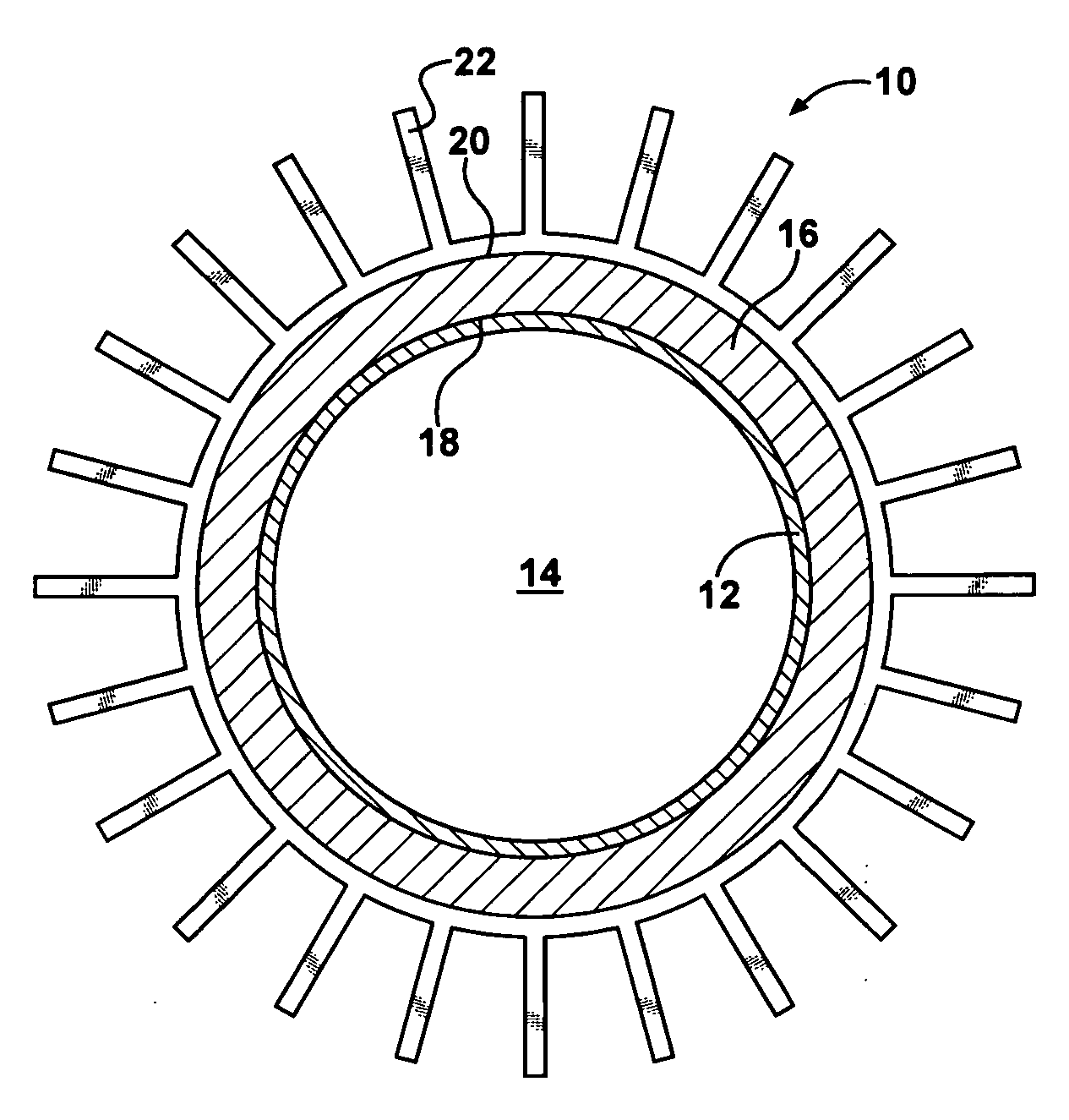
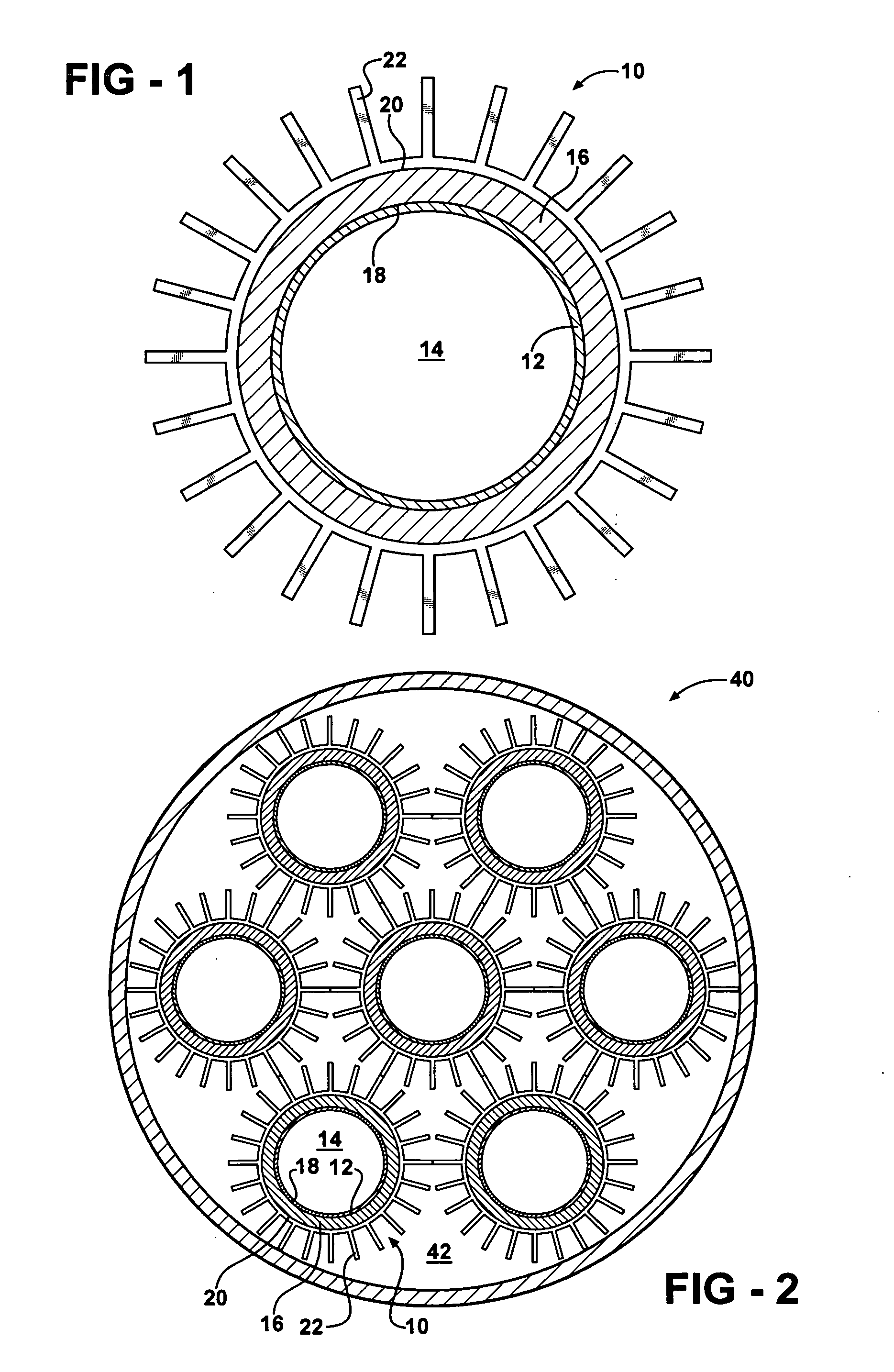
[0018]FIG. 1 shows a cylindrical tube 10 for a heat exchanger 40 illustrated in FIG. 2. The tube 10 has an outer wall 12 with a substantially circular cross-sectional shape. Other cross-sectional shapes can be used as desired. The wall 12 is preferably formed from copper or steel; however, other materials may be used to form the wall 12 without departing from the scope and spirit of the invention. The wall 12 forms a hollow interior portion 14.

[0019]A thermoelectric device (TED) 16 surrounds and is in thermal communication with the wall 12. The TED 16 includes a first heat transfer surface 18 and a second heat transfer surface 20. The first heat transfer surface 18 is in thermal comm...


PUM

PropertyMeasurementUnit
thermoelectricaaaaaaaaaa
heat transferaaaaaaaaaa
thermal efficiencyaaaaaaaaaa

Abstract

A heat exchanger for a vehicle is shown, wherein the heat exchanger includes a plurality of tubes having integrated thermoelectric devices disposed thereon to facilitate heat transfer between the tubes and an atmosphere surrounding the tubes.

Description

FIELD OF THE INVENTION[0001]The present invention relates to a heat exchanger tube and more particularly to a heat exchanger tube having integrated thermoelectric devices to increase a thermal efficiency of the heat exchanger.BACKGROUND OF THE INVENTION[0002]An air-cooled fin-type heat exchanger is very well known. Heat exchangers are used for changing the temperature of various working fluids, such as an engine coolant, an engine lubricating oil, an air conditioning refrigerant, and an automatic transmission fluid, for example. The heat exchanger typically includes a plurality of spaced apart fluid conduits or tubes connected between an inlet tank and an outlet tank, and a plurality of heat exchanging fins disposed between adjacent conduits. Air is directed across the fins of the heat exchanger by a cooling fan or a motion of a vehicle, for example. As the air flows across the fins, heat in a fluid flowing through the tubes is conducted through the walls of the tubes, into the fins...

Claims


Application Information

Patent Timeline
Patent Type & Authority Applications(United States)
IPC IPC(8): F25B21/02
CPCB60H1/00328B60H1/00478B60H1/00557F25B21/02Y10T29/49377F28D7/16F28F13/16H01L35/30F28D1/05316H10N10/13
Inventor GOENKA, LAKHI NANDLAL
Owner GENTHERM INC
Why Eureka
Try Eureka