Calibration Method

a technology for industrial robots and calibration methods, applied in calibration apparatuses, programs, instruments, etc., can solve problems such as errors between correct kinematic robot positions, robot behavior not as correct as possible, and errors related to different sets of calibration equipment, so as to minimize the influence of the mounting of the calibration devi

Inactive Publication Date: 2008-02-07
ABB RES LTD
View PDF6 Cites 23 Cited by
  • Summary
  • Abstract
  • Description
  • Claims
  • Application Information

AI Technical Summary

Benefits of technology

[0005] The object of the present invention is to provide an improved calibration method,

Problems solved by technology

The first group will cause errors between the correct kinematic robot position and the actual robot position.
The result of having cinematic errors is that the robot behavior will not be as correct as possible.
The sec

Method used


Image

  • Calibration Method
  • Calibration Method
  • Calibration Method

Examples


Embodiment Construction

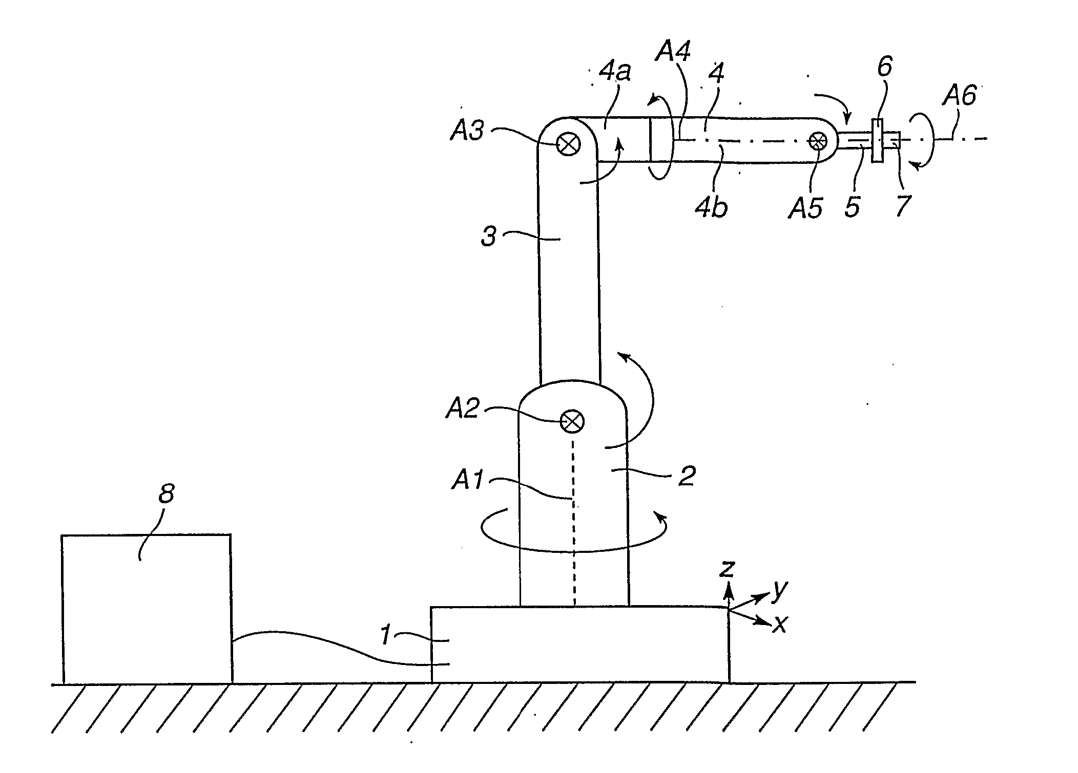
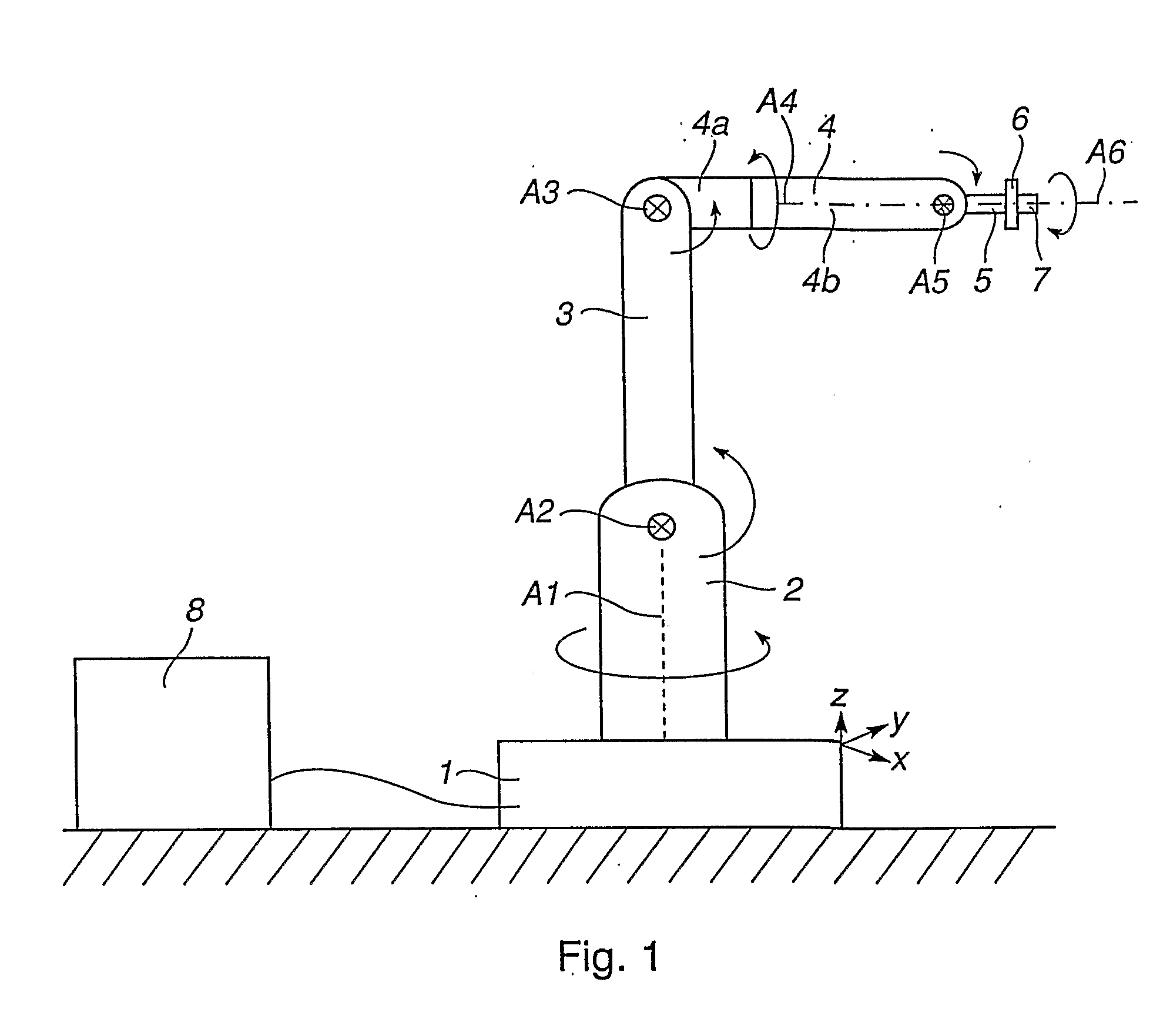
[0032]FIG. 1 shows an example of a 6-axis industrial robot standing in a traditional calibration position, also denoted the home position of the robot. The robot comprises a base 1, which is firmly mounted on a foundation. The robot further comprises a stand 2, which is rotatable relative to the base 1 around a first vertical axis A1. In the top end of the stand 2, a first robot arm 3, is rotatably mounted about a second horizontal axis A2. In the outer end of the first arm 3, a second arm 4 is rotatably mounted relative to the first arm about a third axis A3. The second robot arm 4 comprises two parts, 4a and 4b, and the outer part 4b being rotatable relative to the inner part 4a around a fourth axis A4 coinciding with the longitudinal axis of the second arm 4. In its outer end, the second arm 4 supports a so-called robot hand 5, which is rotatable about a fifth axis A5, which is perpendicular to the length axis of the second arm 4. The robot also comprises a tool attachment 6 in t...


PUM


Abstract

A method for calibration of an industrial robot having a plurality of sections movably connected to each other for rotation about a plurality of movement axes. An angle measuring member is mounted on the robot so that it measures angular changes of the axis or axes to be calibrated, relative to a vertical line. A reference direction is measured. At least one of the axes is selected as a calibration axis and another of the axes is selected as a measuring axis. The robot is moved between at least two calibration positions. The moving includes rotating the robot about the measuring axis. The calibration positions are selected such that the direction of the calibration axis differs from the vertical line. Angular values are read from the angle measuring member in the calibration positions. The calibration axis are calibrated based on the angular values and the measured reference direction.

Description

FIELD OF THE INVENTION AND PRIOR ART [0001] The present invention relates to a method for calibration of an industrial robot according to the preamble of claim 1. [0002] An industrial robot can be viewed as a cinematic chain of sections movably connected to each other about a plurality of rotational axis. The first section in the chain is the base of the robot and the last section usually constitutes a tool attachment. The axis are numbered after their position in the cinematic chain, i.e. the first axis in the chain is denoted the first axis, the next axis is denoted the second axis and so on. For the possibility to determine the position of the robot, each axis usually is provided with an angle-measuring device in the form of an encoder or a resolver indicating the position of the axis relative to a zero position. Before an industrial robot can be used it must be calibrated, which means that each of the angle-measuring devices is calibrated with reference to the zero position. The...

Claims


Application Information

Patent Timeline
IPC IPC(8): G12B13/00B25JB25J9/16
CPCG05B2219/39007B25J9/1692
Inventor BROGARDH, TORGNYFIXELL, PETERDURINDER, NIKLAS
Owner ABB RES LTD
Why Eureka
Try Eureka