
Applicator

Inactive Publication Date: 2008-02-07
VOITH PATENT GMBH
View PDF13 Cites 4 Cited by
  • Summary
  • Abstract
  • Description
  • Claims
  • Application Information

AI Technical Summary

Benefits of technology

[0032] According to a fifth embodiment of the applicator, the jet guide part includes a color guide part for guiding to the guide face incline the color dispensed from the curtain head, and a recovery guide part, which is arranged alongside and in a different direction to the color guide part, for deflecting the flow of surplus color.
[0039] In addition it is possible, owing to the formation of several color layers through lamination in succession on a guide face incline, to achieve a coating with low flow rates and to make color savings.
[0042] According to the fourth embodiment of the applicator, it is possible, on account of the fact that the jet guide part is arranged on the top-most upstream curtain head, for the color flowing in contact with the incline of the guide face to be guided by the jet guide part such that said color flows uniformly over the guide face incline and coating faults are prevented.
[0043] According to the fifth embodiment of the applicator, owing to the fact that the color used for the coating can be guided to the color guide part and to the guide face incline and surplus color can be deflected in its flow and caught by a recovery guide part, an economical and effective use of the colors is achieved.
[0044] According to the sixth embodiment of the applicator, it is possible, owing to the fact that the color used for the coating flows between a pair of flow deflection guide members when it is guided to the guide face incline and the flow of surplus color along the outer side of the pair of flow deflection guide members can be recovered, for an economical and effective use of the colors to be achieved.

Problems solved by technology

However, as described above, there is often a large difference in speed in the case of the color tb, which is to be applied onto the color ta which has already been applied onto the surface of the web w; furthermore, depending on the color type, great differences in surface condition, including the coefficient of friction, arise between the surface of the web w, onto which the color ta is applied, and the color ta, which has been applied onto the surface of the web w and onto which the color tb is to be applied.
If slip occurs between the color tb and the color ta, which has already been applied onto the surface of the web w, then the color tb cannot easily be drawn over the color ta and an irregularity such as spot formation arises in the coating.
Because the curtain application method of the prior art generally requires the formation of independent color curtains, it can also happen, when performing coatings at low speed, that curtains are formed which are unstable and tear easily; consequently, no normal coating can be achieved.
Furthermore, when performing a continuous curtain application using several colors, the coated layers are easily impaired, on account of the thin film thickness of the colors used during the application process, not only by the layer coated underneath but also by the layer coated on top, thus leading to a roughing of the coated surface.
Furthermore, in the case of the application method with displaceable nozzle of the multilayer application method according to the description of the cited publication 1, the feeding of color to the unused heads must be stopped at the end of the application, and if the feeding of color to the unused heads is not stopped, this will lead to mixing of the colors when the device is operated, and the colors can no longer be recovered independently.
Although no mixing of the colors occurs during operation of the machine, when the feeding of color to the unused heads is stopped, then the colors will dry out in the unused nozzle head parts and stick to the heads because the colors cannot be circulated.
Hence during subsequent operations performed when color is stuck to the heads, this soiling of the heads leads to the formation of streak patterns, clogging of the nozzle slit and the non-uniform feeding of color in the width direction.
Changing the type of product to be coated thus involves a great amount of time because the application process must also be stopped of course and all the heads must be cleaned.
As such, the multilayer application method with displaceable nozzle is problematic inasmuch as it results in a mixing of the colors, controlling the colors of each layer is difficult, all the heads have to be cleaned when a change of application is performed, and the process of starting and stopping the application is difficult.

Method used


Image

  • Applicator
  • Applicator
  • Applicator

Examples


Embodiment Construction

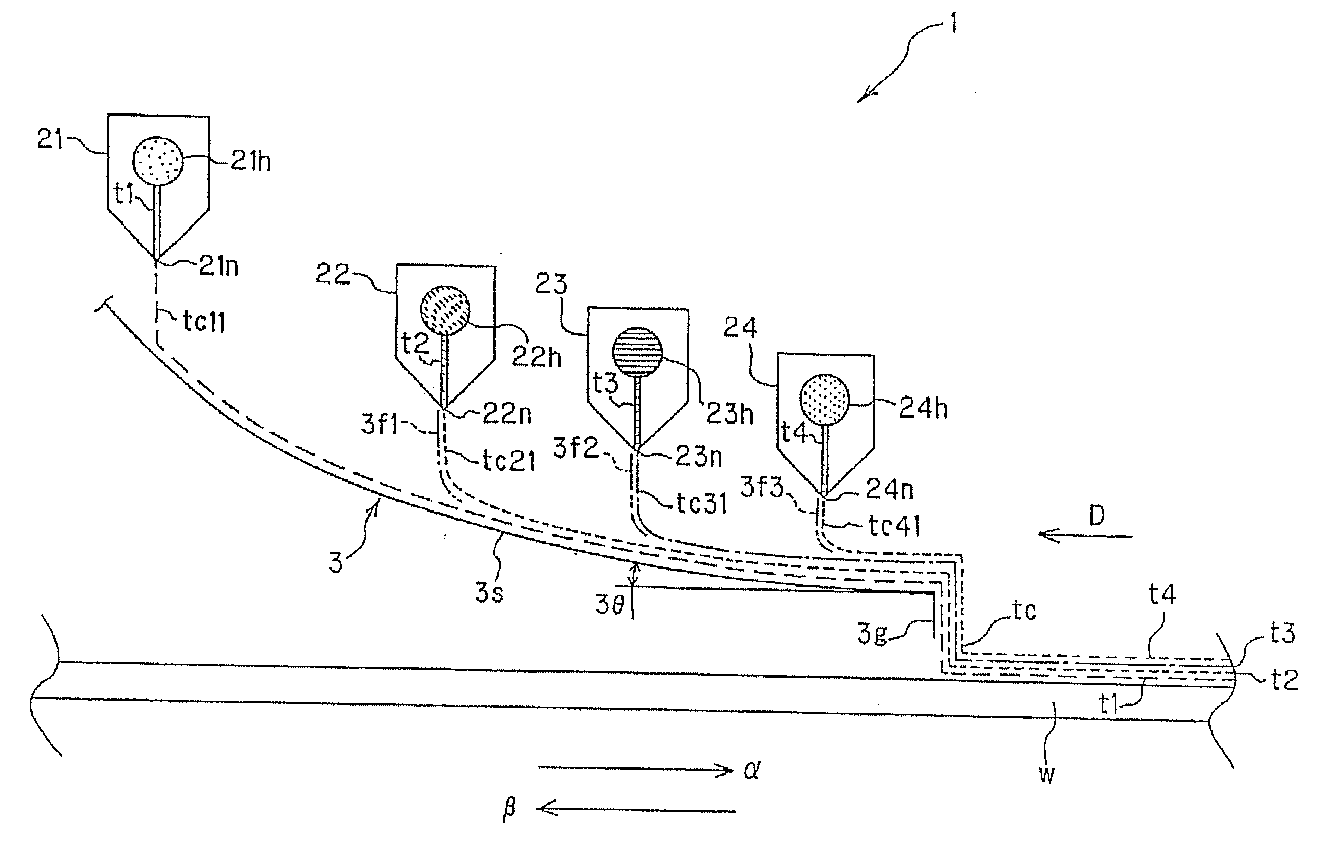
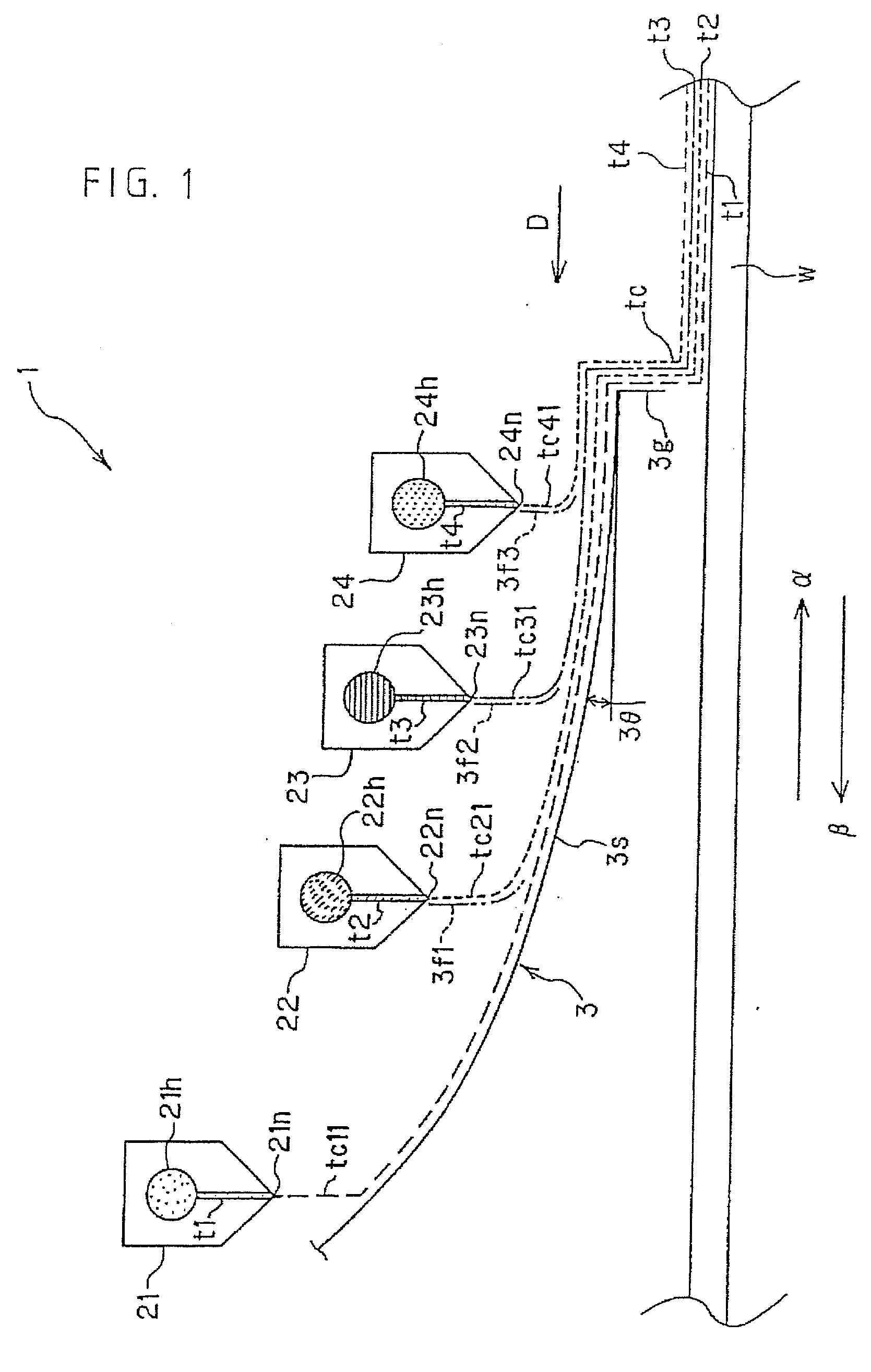
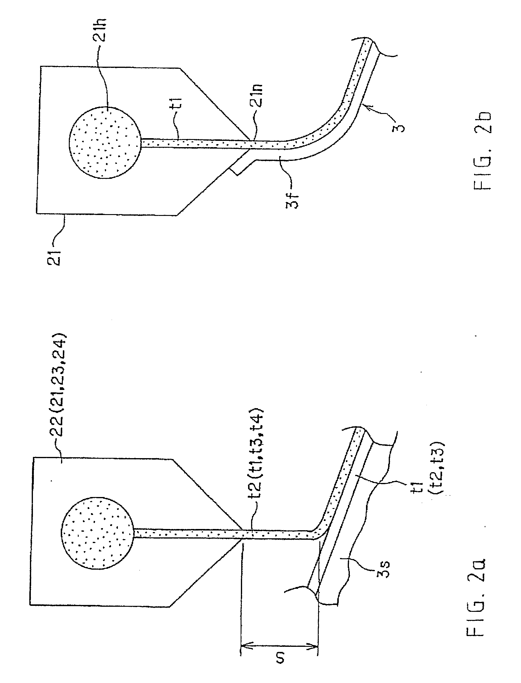
[0066] Referring now to the drawings, and more particularly to FIG. 1, there is shown a schematic cross section of an applicator 1 on which the current invention finds application. The device in FIG. 1 forms a device on which, during running in the direction of an arrow α (or an arrow β) of a web w to be coated, various colors t1, t2, t3, t4 are laminated on one side of the web w, as the result of which four applied layers are formed.

[0067] Although FIG. 1 presents an example in which four applied layers are used, it is also possible for two, three or five or more layers to be used.

[0068] The applicator 1 includes a first curtain head 21 for dispensing a first coating medium, e.g. a first color t1, and forming a medium or color curtain tc1, a second curtain head 22 for dispensing a second medium or a second color t2 and forming a medium or color curtain tc2, a third curtain head 23 for dispensing a third medium (hereinafter referred to only as “color” . . . for the sake of simplic...


PUM


Abstract

This invention relates to an applicator for applying coating medium, in particular coating medium in several layers onto a running web surface. The applicator includes several curtain heads, which are arranged at random distances apart and from which the coating media or colors are dispensed downward, and an inclined guide face which—as the result of lamination of the coating media or colors dispensed one after the other from each of the several curtain heads along the incline in order to form the several medium or color layers and, in addition, to form a color curtain from a curtain guide part pointing downwards—moves the color layers at the end of the part of the incline onto the web surface.

Description

CROSS REFERENCE TO RELATED APPLICATIONS [0001] This is a continuation of PCT application No. PCT / EP2006 / 050424, entitled “APPLICATION DEVICE”, filed Jan. 25, 2006, which is incorporated herein by reference.BACKGROUND OF THE INVENTION [0002] 1. Field of the Invention [0003] This invention relates to an applicator for applying coating medium, for example color, in several layers onto a running web. [0004] 2. Description of the Related Art [0005] Up to now it was necessary, during the production of coated paper for use as general printing paper, for example for catalogs etc., pressure-sensitive paper, heat-sensitive paper and card paper for automatic card dispensing machines, to carry out dosing operations by way of a standard post-dosing applicator (a doctor coating unit etc.) after applying color onto a web surface acting as base paper. Machines which are used for such applications of color are commonly known as applicators. [0006] Up to now the most common of these applicators, name...

Claims


Application Information

Patent Timeline
IPC IPC(8): B05C5/00B05C3/02B05C3/12
CPCB05C5/005B05C9/06B05C5/008
Inventor MORITA, HIROFUMINAKAZAWA, TAKEOITOH, JUNICHI
Owner VOITH PATENT GMBH
Learn More