
Method Of Moistening Paper Web And Paper Web Moistening Device

Inactive Publication Date: 2008-02-07
METSO AUTOMATION OY (FI)
View PDF5 Cites 15 Cited by
  • Summary
  • Abstract
  • Description
  • Claims
  • Application Information

AI Technical Summary

Benefits of technology

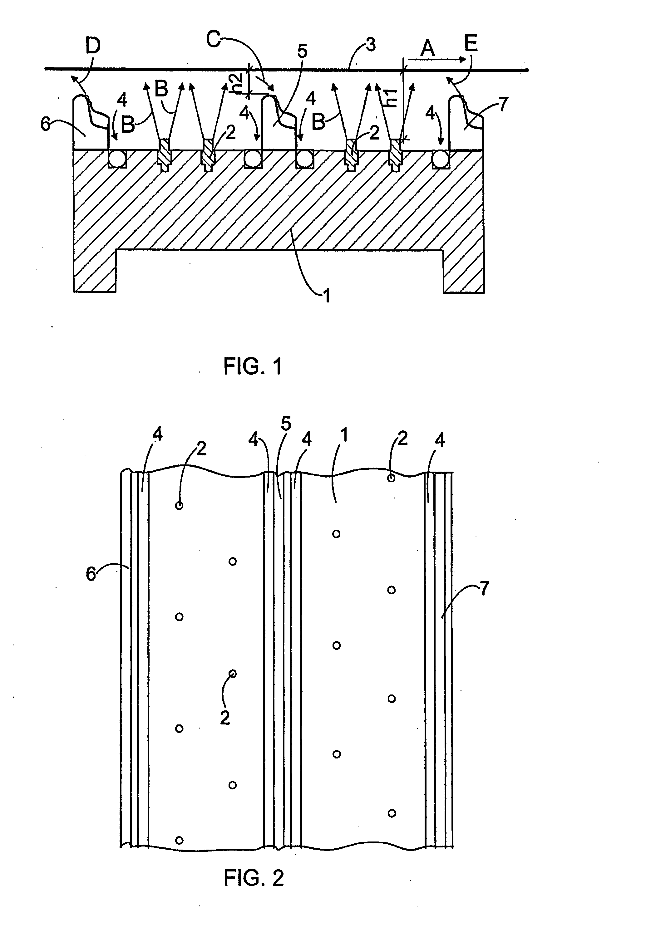
[0009] The basic idea of the invention is that several moistening nozzles are arranged in the body of the paper web moistening device. At least one means for removing water mist and / or air from the vicinity of the paper web surface is arranged between the moistening nozzles so that the means extends closer to the paper web than the moistening nozzle. By means of the invention, the desired moisture profile can be achieved with a very high accuracy. Furthermore, the detrimental effect of air currents on moisture nozzle responses can be prevented, which facilitates the controlling of the moistening device. The idea of an embodiment is that the means for removing water mist and / or air from the vicinity of the paper web surface is a discharge nozzle. The idea of another embodiment is that before the moistening nozzles, the moistening device comprises a slit nozzle having substantially the same width as the paper web for blowing air against the machine direction of the paper web to decrease the laminar air current travelling along with the paper web. The purpose of this is also to improve the moisture profile produced by the moistening device. The idea of a third embodiment is that the nip side of the moistening device is provided with a slit nozzle having substantially the same width as the paper web for blowing air in the direction opposite to the machine direction of the paper web to prevent water mist from spreading into the environment from the moistening device.

Problems solved by technology

A problem associated with moistening devices is how to achieve a sufficiently even moistening result.
The air currents generated make the controlling of the moistening nozzle response difficult, i.e. the fact which point of the paper web is in reality moistened by moistening nozzle.
In the moistening device, the current may cause the nozzles at different points in the lateral direction to moisten the same point of the paper web, which results in too moist and too dry points in the paper web.
Furthermore, the controlling of the moistening nozzle response is so difficult that the adjustment of the moistening nozzles becomes very complicated.

Method used


Image

  • Method Of Moistening Paper Web And Paper Web Moistening Device
  • Method Of Moistening Paper Web And Paper Web Moistening Device

Examples


Embodiment Construction

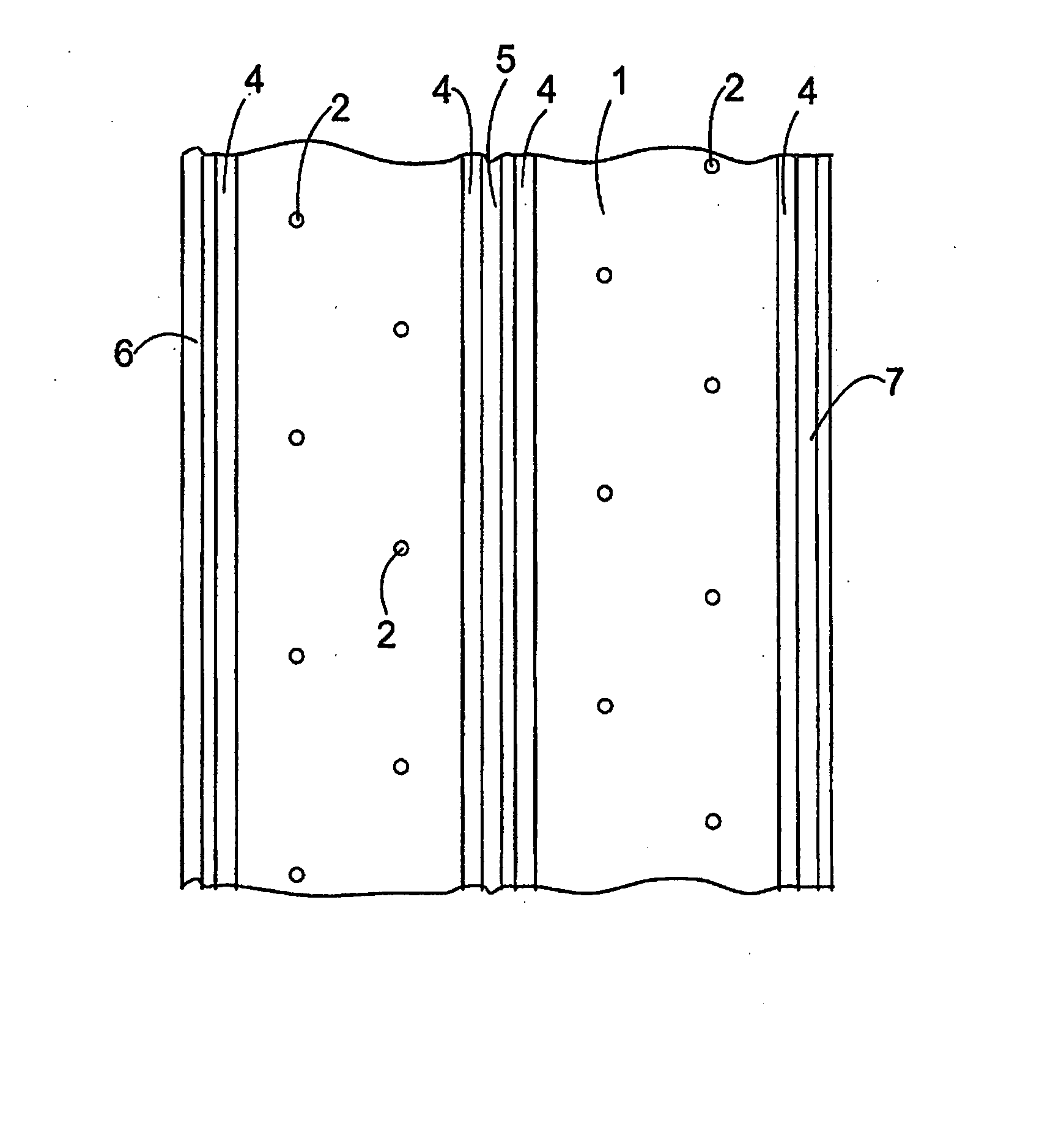
[0015]FIG. 1 illustrates a paper web moistening device where the body 1 is provided with moistening nozzles 2. The body 1 is a beam arranged in the cross direction of the paper web 3. The moistening device is arranged below the paper web 3. The paper web 3 moves in the direction of arrow A. The paper web 3 may be a paper or cardboard web already manufactured in a paper machine or a fibrous web in a paper machine or cardboard machine, still containing moisture that is to be removed in the paper machine. The moistening device is typically arranged below the paper web 3, but if desired, it may also be mounted above the paper web 3 or both above and below the paper web. The particular purpose of the moistening device is to increase the moisture content of the paper web 3.

[0016] Water mist is blown or sprayed by moistening nozzles 2 towards the paper web 3 surface, the water mist being typically a mixture of air and water. The cone-shaped water mist spray achieved by means of the moiste...


PUM

PropertyMeasurementUnit
Distanceaaaaaaaaaa
Distanceaaaaaaaaaa
Widthaaaaaaaaaa

Abstract

A paper web moistening device comprises several moistening nozzles (2) in the cross direction of a paper web for blowing water mist comprising air and water onto the paper web (3) surface. At least one means for removing water 5 mist and / or air from the vicinity of the paper web (3) surface is arranged be-tween the moistening nozzles. This means is arranged closer to the paper web (3) surface than the moistening nozzles (2).

Description

BACKGROUND OF THE INVENTION [0001] The invention relates to a method of moistening a paper web comprising moistening the paper web by a moistening device by spraying water mist onto the paper web surface and by removing excess water mist from the moistening device. [0002] The invention further relates to a paper web moistening device comprising a body, moistening nozzles and at least one means for removing water, water mist or air from the moistening device. [0003] The paper web is moistened to control the paper web moisture profile, for instance. Moistening can also be used for managing the curling of the paper web in the paper machine. Furthermore, in online calendering, for example, the controlling of certain quality measures requires high-grade moistening with water. [0004] The moistening device is provided with several moistening nozzles in the cross direction of the paper web for blowing water mist containing air and water onto the paper web surface. One moistening apparatus o...

Claims


Application Information

Patent Timeline
IPC IPC(8): D21H23/02D21H23/20
CPCD21F7/008D21G7/00D21G1/0093
Inventor LATTI, HANNUKETTUNEN, HEIKKIHEIKKINEN, ANTTIPOSTI, NIKOALMI, JARI
Owner METSO AUTOMATION OY (FI)
Learn More