Control circuit and method for a constant on-time PWM switching converter

a technology of pwm switching converter and control circuit, which is applied in the direction of electric variable regulation, process and machine control, instruments, etc., can solve the problems of increasing the switching loss of switches sw, slow response to load transients, and reducing the efficiency of converters, so as to improve the efficiency reduce the recovery time of a constant on-time pwm switching converter. , the effect of reducing the loss

Active Publication Date: 2008-02-07
RICHTEK TECH
View PDF7 Cites 64 Cited by
  • Summary
  • Abstract
  • Description
  • Claims
  • Application Information

AI Technical Summary

Benefits of technology

[0007]Another object of the present invention is to provide a control circuit and method for decreasing the switching loss in a transient state of a constant on-time PWM switching converter.
[0008]Still another object of the present invention is to provide a control circuit and method for improving the efficient of a constant on-time PWM switching converter.
[0009]Yet another object of the present invention is to provide a control circuit and method for reducing the recovery time of a constant on-time PWM switching converter.
[0010]Still yet another object of the present invention is to provide a control circuit and method for speeding up the transient response of a constant on-time PWM switching converter.

Problems solved by technology

It causes that in the control signal UG, the constant on-time Ton and the minimum off-time Toff_min are alternatively triggered instantly, without more time therebetween for the off-time, which increases the switching frequency during the transient state, resulting in more switching loss of the switches SW1 and SW2, and so decreasing the efficiency of the converter.
Moreover, during the transient state, because the on-time Ton for the output voltage Vout to increase is constant, it needs more switching cycles or longer time interval for the output voltage Vout to recover to the previous level, and thus the response to the load transient will be slow.

Method used


Image

  • Control circuit and method for a constant on-time PWM switching converter
  • Control circuit and method for a constant on-time PWM switching converter
  • Control circuit and method for a constant on-time PWM switching converter

Examples


Embodiment Construction

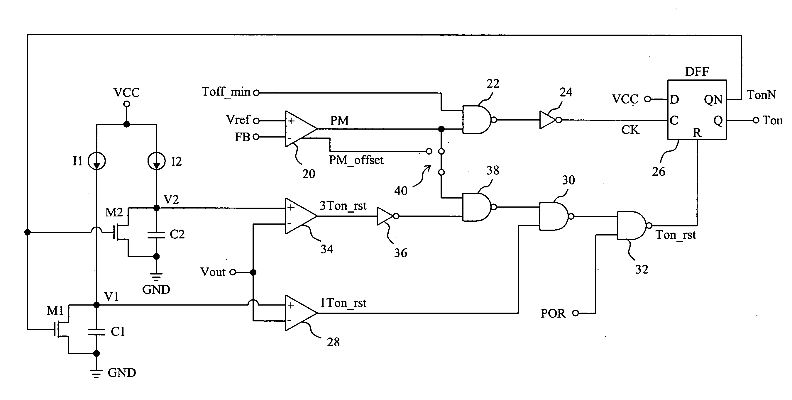
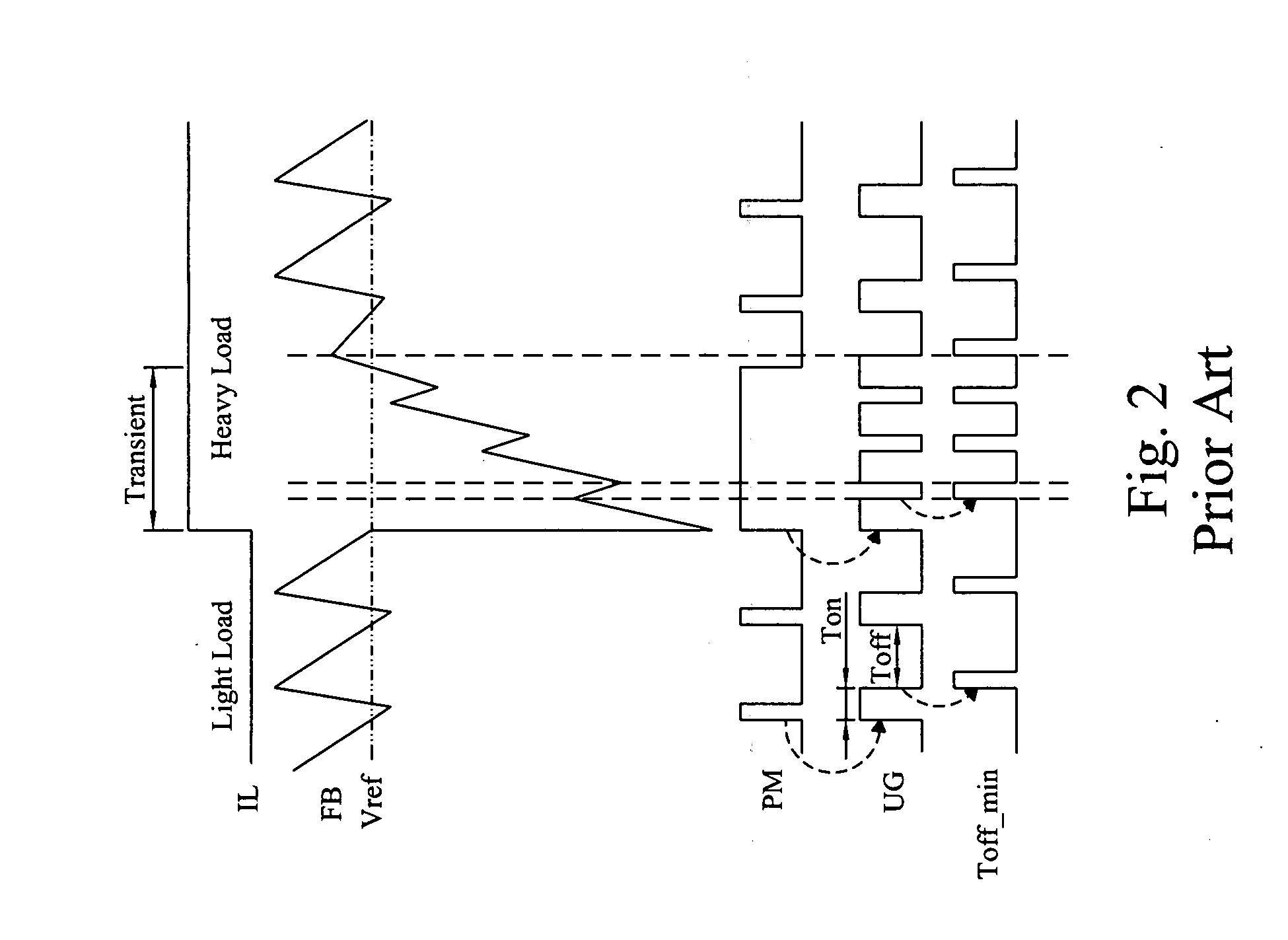
[0028]FIG. 3 shows a control method for a constant on-time PWM switching converter according to the present invention. In steady state, the operation of a constant on-time PWM switching converter under this control is the same as that of FIG. 2, i.e., a constant on-time Ton is followed by an off-time Toff, and the off-time Toff is terminated when the next on-time Ton is triggered. Whereas, in load transient, the on-time will be prolonged if the pulse modulation signal PM is still at high level. The length of the on-time can be prolonged to be infinite, or to be shorter than a predetermined limit, for example the triple of the constant on-time Ton, i.e., 3Ton. When a load transient happens, the feedback signal FB falls down lower than the reference signal Vref, which triggers the pulse modulation signal PM to high level, and further triggers the control signal UG to high level. The control signal UG keeps at high level until the prolonged on-time reaches the predetermined maximum, fo...


PUM


Abstract

A control circuit provides a control signal for a constant on-time PWM switching converter to produce an output voltage, such that the converter operates with a constant on-time at a first state and operates with a variable on-time at a second state, so as to decrease the switching frequency and thereby the switching loss, to increase the efficiency of the converter, to improve the transient response, and to reduce the recovery time of the output voltage.

Description

FIELD OF THE INVENTION[0001]The present invention is related generally to a power converter and, more particularly, to a constant on-time pulse width modulation (PWM) switching converter.BACKGROUND OF THE INVENTION[0002]Switching converters are widely used in various electronic products for providing stable direct-current (DC) voltages for load circuits such as central processing unit (CPU). FIG. 1 shows a conventional synchronous buck converter 10, in which a control circuit 12 produces two control signals UG and LG to switch an upper switch SW1 and a lower switch SW2 in a power stage 14 so as to convert an input voltage Vin to an output voltage Vout, and by detecting the output voltage Vout a feedback signal FB is fed back to the control circuit 12 for regulating the output voltage Vout. FIG. 1 also shows a power stage 16 of a synchronous boost converter and a power stage 18 of a synchronous inverting converter. If the switches SW2 in the power stages 14-18 are replaced by diodes,...

Claims


Application Information

Patent Timeline
Patent Type & Authority Applications(United States)
IPC IPC(8): G05F1/44G05F1/00
CPCH02M3/157Y02B70/1491H02M2001/0048H02M1/0048Y02B70/10
Inventor LIU, KUO PINGWANG, KO CHENGTAI, LIANG PINCHENG, CHUNG SHENG
Owner RICHTEK TECH
Why Eureka
Try Eureka