Light emitting apparatus

a technology of light-emitting devices and led chips, which is applied in the direction of light-emitting devices, solid-state devices, semiconductor devices, etc., can solve the problems of cracks or peeling at the interface between the resinous members, deterioration of the led device characteristics, and the disconnection of the au (gold) wires connecting the led chip to the circuit board, so as to achieve the effect of effectively preventing cracks

Inactive Publication Date: 2008-02-07
CITIZEN ELECTRONICS CO LTD
View PDF9 Cites 32 Cited by
  • Summary
  • Abstract
  • Description
  • Claims
  • Application Information

AI Technical Summary

Benefits of technology

[0014] An object of the present invention is to provide a light emitting apparatus in which peeling due to heat stress or th...

Problems solved by technology

Heat generated by applying a higher current and sunlight may deteriorate characteristics of the LED device over time.
Also, when the LED devices are subject to reflow process, there are cases in which cracks or peeling may occur at the interface between the resinous member sealing the LED chip and the lens part because of different coefficients of heat expansion of the sealing member and the lens part.
Also, cracks may lead to breakdown; in p...

Method used


Image

  • Light emitting apparatus
  • Light emitting apparatus
  • Light emitting apparatus

Examples


first embodiment

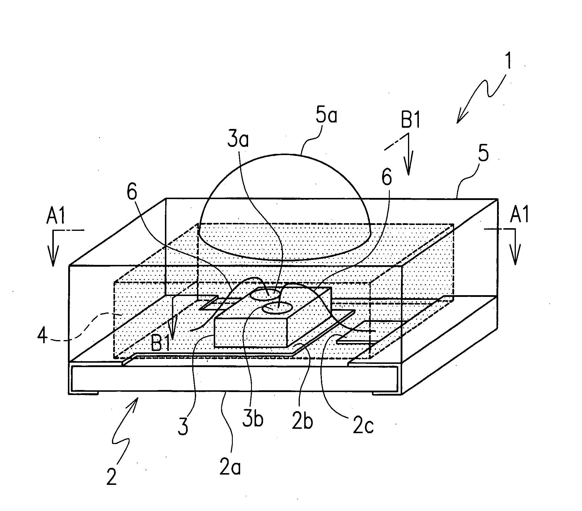
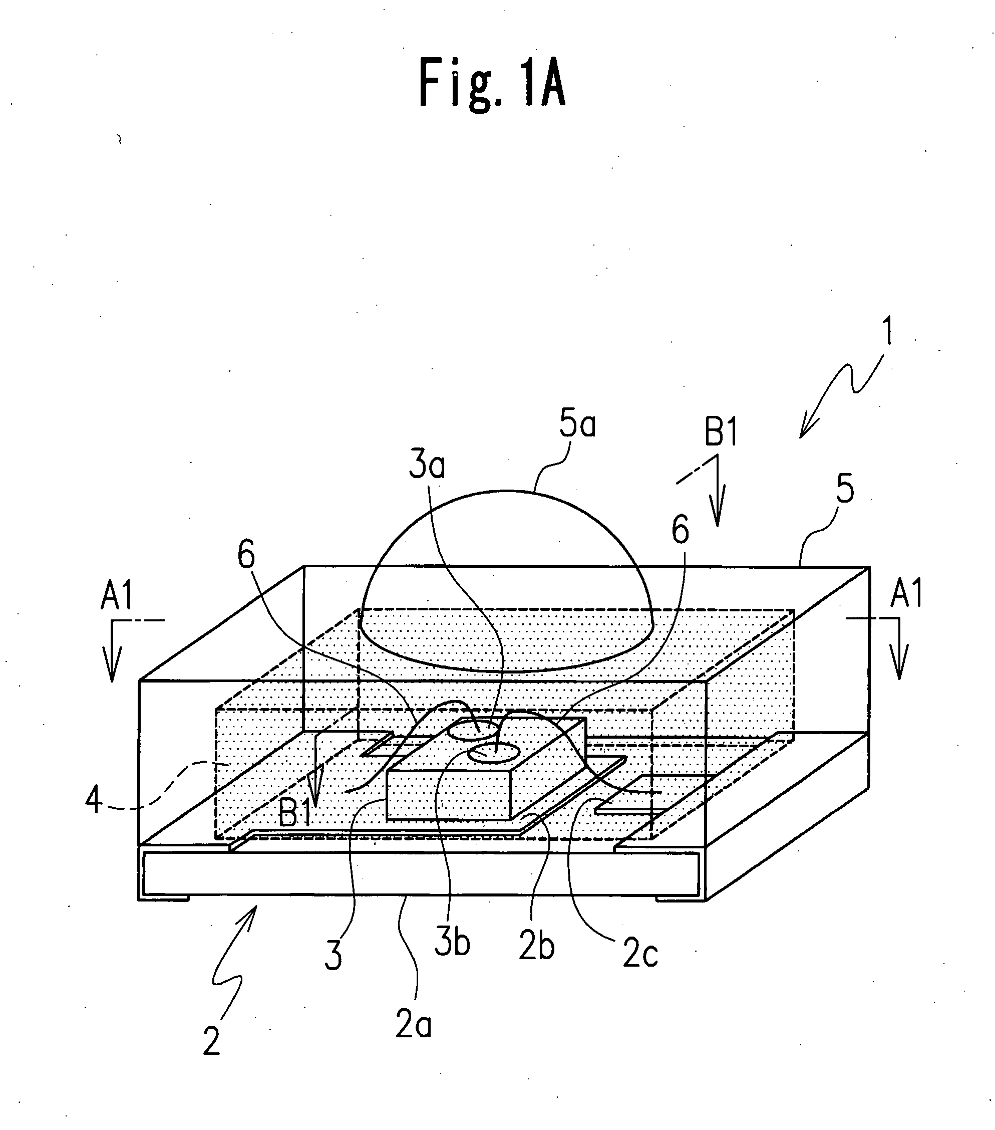
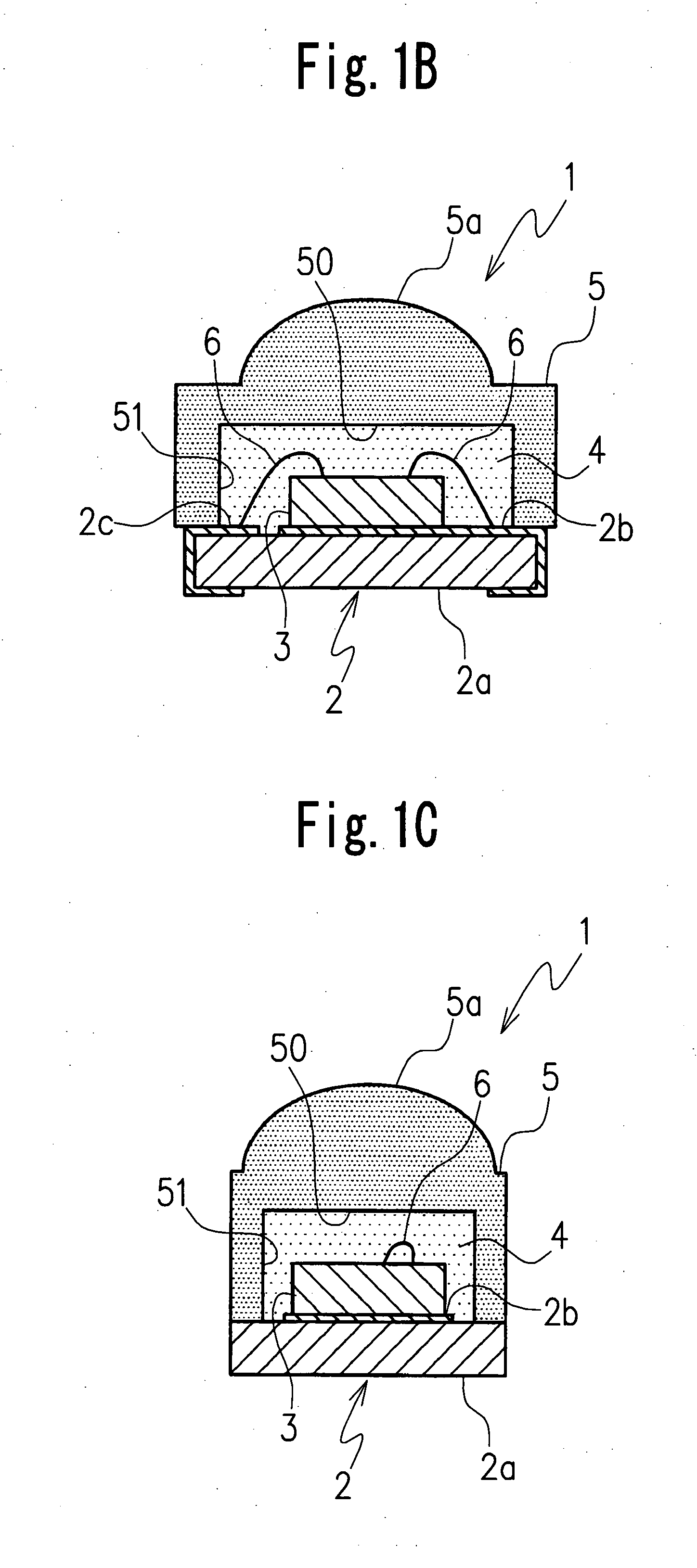
[0029]FIGS. 1A, 1B and 1C show a light emitting apparatus according to the present invention.

[0030] The light emitting apparatus 1 in the first embodiment is applied to a white LED device which is used, for example, as a supplementary light source to facilitate the capturing of a moving image with a mobile phone or as a light source for general lighting. However, the light emitting apparatus according to the present invention can be applied to devices other than the white LED device.

[0031] The light emitting apparatus 1 includes a board or circuit board 2, at least one LED element 3 mounted on one surface, for example, an upper surface of the circuit board 2, a first resinous sealing member 4 to seal the LED element 3 and a second resinous sealing member 5 to cover the first resinous sealing member 4.

[0032] The circuit board 2 includes a main body 2a having a generally rectangular solid-like shape, and an anode electrode pattern 2b and a cathode electrode pattern 2c which are patt...

second embodiment

[0060] In other words, in the light emitting apparatus 11 shown in the second embodiment, the second resinous sealing member 15 includes a pair of supporters 16a which are provided on both sides where the anode electrode pattern 2b and the cathode electrode pattern 2c are disposed and adhered to the circuit board 2 (see FIG. 2B).

[0061] Consequently, a concave portion 61 to contain the first resinous sealing member 14 is formed between the pair of supporters 16a. The pair of supporters 16a extend from both sides of the second resinous sealing member 15 to fringes of the circuit board 2.

[0062] The first resinous sealing member 14 is exposed from the second resinous sealing member 15 at sides except the pair of supporters 16a being disposed.

[0063] In this second embodiment, when a plurality of light emitting apparatuses 11 are produced simultaneously, LED element 3 is mounted one- or two-dimensionally on each of the circuit boards 2, because the concave portions adjacent to each othe...

third embodiment

[0065] More specifically, the first resinous sealing member 24 is exposed at sides except the pair of supporters 16a being disposed. In the light emitting apparatus 21 shown in the third embodiment, the first resinous sealing member 24 is exposed at upper portion of sides except the pair of supporters 16a being disposed (see FIG. 3C).

[0066] In other words, in the light emitting apparatus 21 shown in the third embodiment, the second resinous sealing member 25 includes a window 25a which is provided at each of both sides of the second resinous sealing member 25 where the anode electrode pattern 2b and the cathode electrode pattern 2c are not disposed and is configured to open about half of a thickness of the second resinous sealing member 25, as shown in FIG. 3C.

[0067] The LED element 3 is sealed in a state in which the first resinous sealing member 24 is filled in a concave portion 71 surrounded by the circuit board 2 and the second resinous sealing member 25.

[0068] In the third em...


PUM


Abstract

A light emitting apparatus including a board (2), at least one LED element (3) mounted on the board (2), a first resinous sealing member (4) to seal the LED element (3) and having a linear coefficient of expansion, and a second resinous sealing member (5) to cover the first resinous sealing member (4) and having a linear coefficient of expansion, the first resinous sealing member (4) containing a functional additive comprising at least one of a fluorescent material, an inorganic filler, and a diffusing agent, the linear coefficient of expansion of the first resinous sealing member (4) being set to be substantially identical with the linear coefficient of expansion of the second resinous sealing member (5).

Description

CROSS-REFERENCE TO THE RELATED APPLICATION [0001] This application is based on and claims priority from Japanese Patent Application No. 2006-045302, filed on Feb. 22, 2006, the disclosure of which is incorporated herein by reference in its entirety. BACKGROUND OF THE INVENTION [0002] 1. Field of the Invention [0003] The present invention relates to a light emitting apparatus suitable to, for example, as a supplementary light source to facilitate the capturing of moving images with a mobile phone, or as a light source for general lighting. [0004] 2. Description of Related Art [0005] In recent years, white LED devices containing blue LED chips or ultra-violet LED chips have been used, for example, as a supplementary light sources to facilitate the capturing of moving images with mobile phones, as light sources for general lighting, and as light sources in the head light of vehicles, or the like. [0006] Many of these white LED devices include a resinous sealing member to seal an LED ch...

Claims


Application Information

Patent Timeline
IPC IPC(8): F21V7/04H01L33/32H01L33/34H01L33/50H01L33/54H01L33/56H01L33/62
CPCH01L33/52H01L33/58H01L2224/45144H01L2224/48091H01L2924/00014H01L2924/00
Inventor KODAIRA, HIROSHIISHIZAKA, MITSUNORIIMAI, SADATO
Owner CITIZEN ELECTRONICS CO LTD
Why Eureka
Try Eureka