Camera Calibration Method And Camera Calibration Device

Active Publication Date: 2008-02-07
AISIN SEIKI KK
View PDF5 Cites 113 Cited by
  • Summary
  • Abstract
  • Description
  • Claims
  • Application Information

AI Technical Summary

Benefits of technology

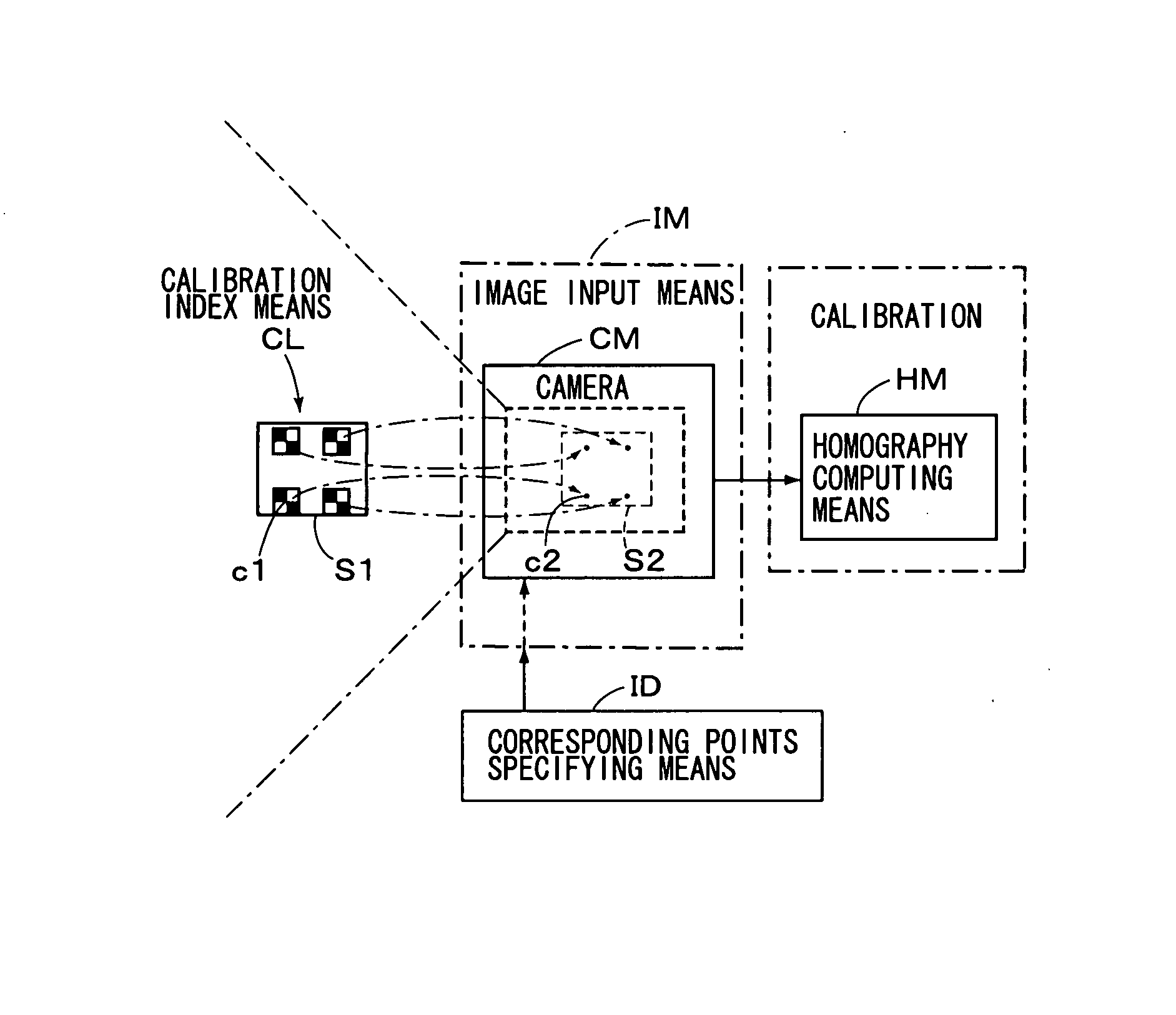
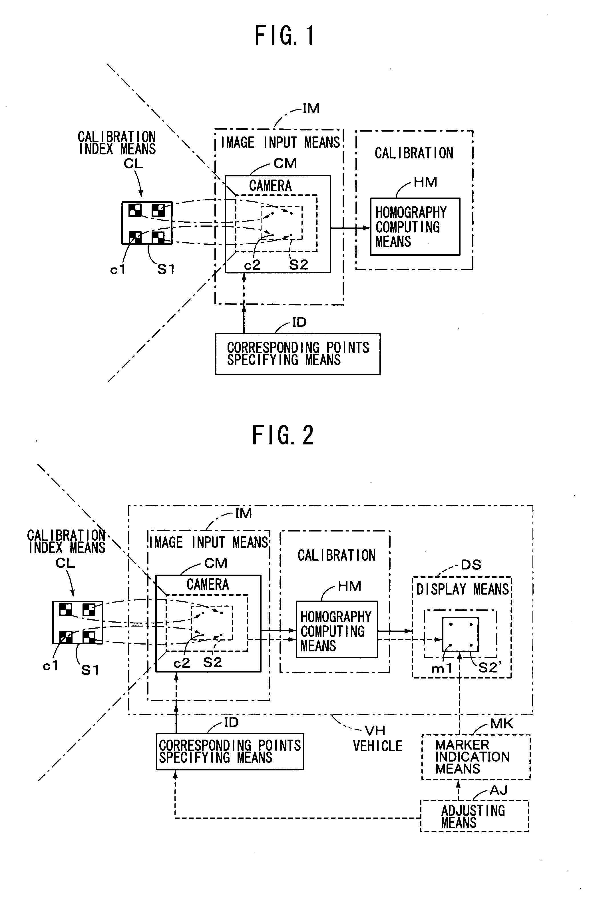
[0021] As the present invention is constituted as described above, the following effects will be achieved. That is, according to the above-described camera calibration method, since it is so constituted to employ the four points whose arrangement on the plane in the three-dimensional space are known, as the calibration indices, and obtain the transforming relationship of the four points between two images by the homography, the camera extrinsic parameters such as the camera focal length, original position or the like, may be unknown, and also the camera extrinsic parameters may be unknown, so that calibration at high accuracy can be practiced by the easy method.
[0022] Also, according to the above-described camera calibration device, since it is so constituted to employ the four points whose arrangement on the plane in the three-dimensional space are known, as the calibration indices, and perform corresponding the four points between two images by the homography, even if both of the camera intrinsic parameters and extrinsic parameters were unknown, the four points on the camera image could be recovered appropriately, as the four points on the plane in the original three-dimensional space. In this case, since the camera intrinsic parameters such as the camera focal length, original position or the like, may be unknown, and also the camera extrinsic parameters, which correspond to information of the position and behavior of the camera in the three-dimensional space, may be unknown, the requisites for mount

Problems solved by technology

In the production site, if the method for performing the calibration by placing the featured three-dimensional objec

Method used


Image

  • Camera Calibration Method And Camera Calibration Device
  • Camera Calibration Method And Camera Calibration Device
  • Camera Calibration Method And Camera Calibration Device

Examples


Example

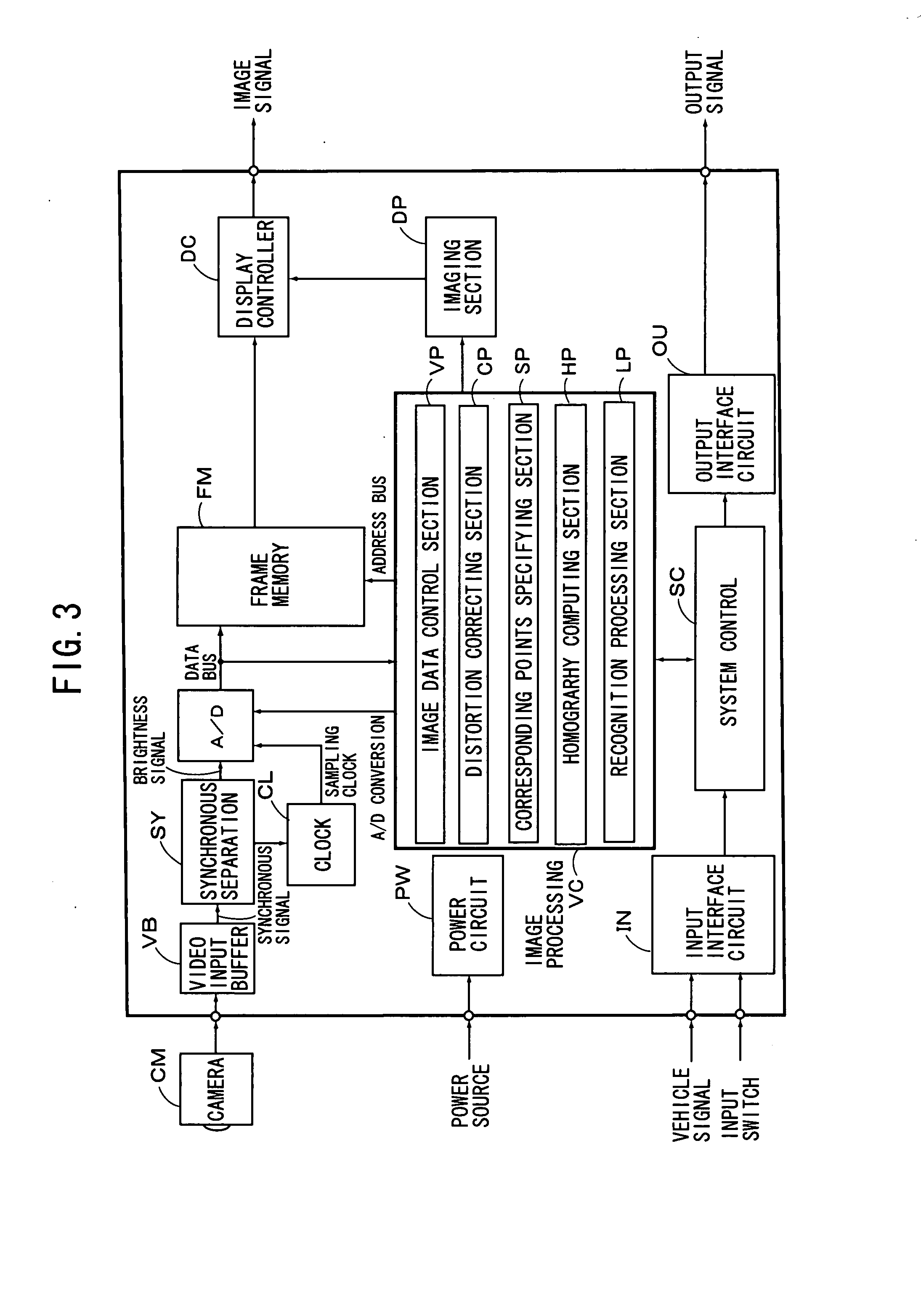
[0044] CM: camera [0045] IM: image input means [0046] HM: homography computing means [0047] ID: corresponding points specifying means [0048] DS: display means [0049] MK: marker indication means [0050] AJ: adjusting means [0051] SY: synchronous separation circuit [0052] FM: frame memory [0053] VC: image processing section

BEST MODE FOR CARRYING OUT THE INVENTION

[0054] A practical embodiment of the camera calibration method of the present invention as constituted above will be explained hereinafter with reference to the drawings. First of all, a camera technique provided as a background of the present invention is explained referring to FIGS. 17-20, thereafter the embodiment of the present invention will be explained referring to FIGS. 1 and 2. At the outset, a camera coordinate system is defined as shown in FIG. 17. That is, as explained in the Non-patent document 3, an optical center (C) of a camera is provided as an origin of coordinates, X-axis and Y-axis of 3D coordinates are pr...


PUM


Abstract

Planar calibration indices (c1) including coordinate information of at least four points are placed on a first plane (S1), and an image plane of the camera image including the calibration indices is input as a second plane (S2). Points (c2) existing on the second plane and corresponding to predetermined portions of the calibration indices are specified, and homography between the first plane and the second plane is computed, on the basis of the corresponding relationship of the at least four points included commonly in the first plane and the second plane, so that the camera image is calibrated. For example, a device is mounted on a vehicle, and four points, whose arrangement on a plane in 3D space is known, are used as calibration indices, and corresponding four points on the camera image, which correspond to them respectively, is achieved automatically.

Description

TECHNICAL FIELD [0001] The present invention relates to a camera calibration method and a camera calibration device, and particularly relates to the camera calibration method and camera calibration device for performing calibration to a camera image by a camera for projecting 3D space onto 2D image. BACKGROUND ART [0002] As for a camera calibration method, various proposals have been made heretofore, one of which is known as a method for computing camera parameters, by placing a featured three-dimensional object, whose configuration has been known in advance, in 3D space, as an index for calibration, and determining how featured points of the three-dimensional object are indicated on a camera image coordinate system. [0003] For instance, in Non-patent document 1, there is disclosed a method for computing camera parameters with 11 degrees of freedom, by means of calibration indices for the featured three-dimensional object. In this respect, proposed is a method for determining calibr...

Claims


Application Information

Patent Timeline
IPC IPC(8): G06T17/20
CPCG06T7/0018G06T7/80B60R1/00G03B15/00H04N7/18H04N13/00
Inventor KAKINAMI, TOSHIAKI
Owner AISIN SEIKI KK
Why Eureka
Try Eureka