Wide-Field Image Input Method And Device

Active Publication Date: 2008-02-07
NEC CORP
View PDF2 Cites 20 Cited by
  • Summary
  • Abstract
  • Description
  • Claims
  • Application Information

AI Technical Summary

Benefits of technology

[0018] According to the present invention, while the series of images is taken with the imaging device, e.g., a camera, by the user, when there is a possibility in that the quality of images degrades caused by user's scanning mistake such as that the camera is significantly tilted or the distance from the imaging object is remarkably varied, that effect can be notified to the user before such a scanning mistake is taken. Accordingly, the deterioration in the quality of mosaic images caused by user's scanning mistake is reduced, and a wide-field image ca

Problems solved by technology

When a paper surface, such as magazines, newspapers, and books, is imaged by an imaging device, e.g. camera, there is a case where the number of pixels in an image pickup element device is insufficient to image a desired range on the paper surface in a desired resolution.
This problem occurs more remarkably, when a relatively close object is imaged by manual camera scan (i.e., the object is scanned while the camera is moved), for example, the paper surface of newspapers or magazines is imaged, namely, when the object is close to the camera and is imaged at a wide-angle.
However, when an object relatively close to the camera is imaged, hand shakes or the like have a profound effect.
Further, when the camera is excessively tilted, the image is taken in a manner that the paper surface has different resolutions in different points in spite of one partial image.
However, no method is carried out such that user's camera scan is guided so as not to generate resolution variations on

Method used


Image

  • Wide-Field Image Input Method And Device
  • Wide-Field Image Input Method And Device
  • Wide-Field Image Input Method And Device

Examples


Example

First Embodiment

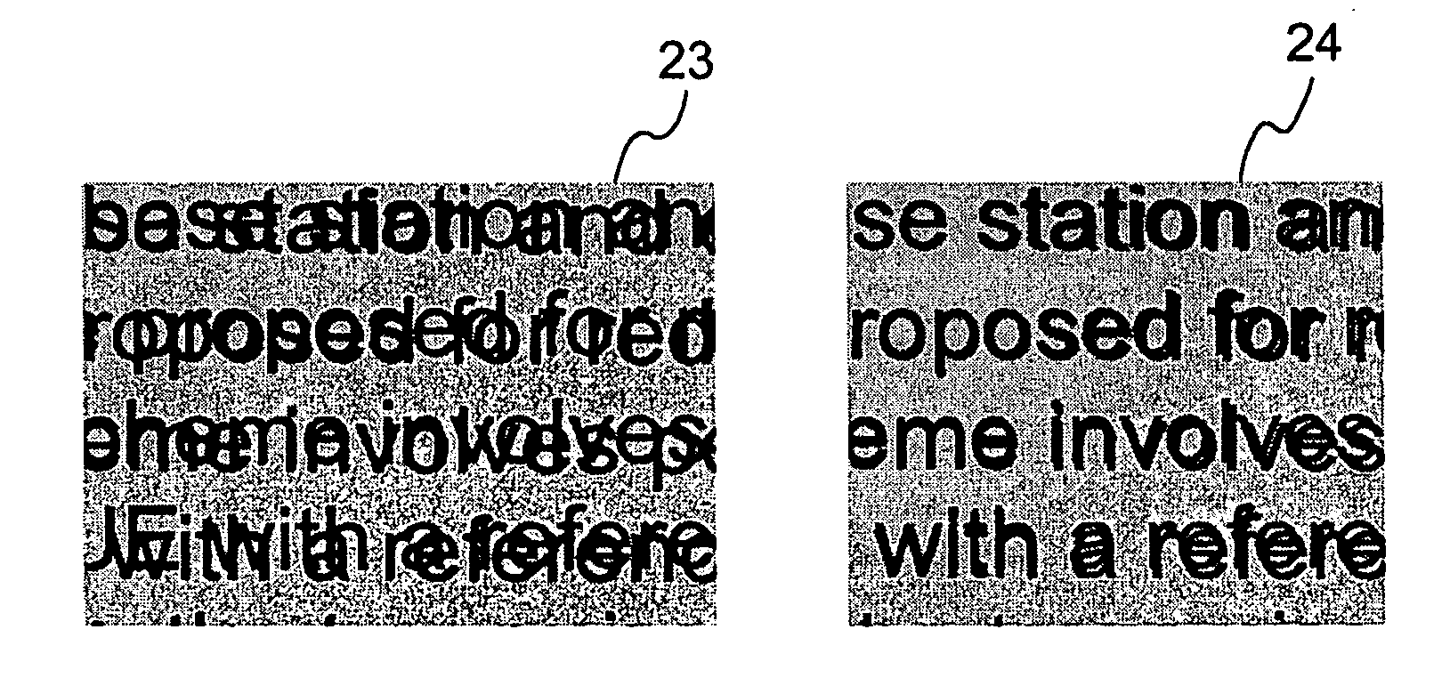
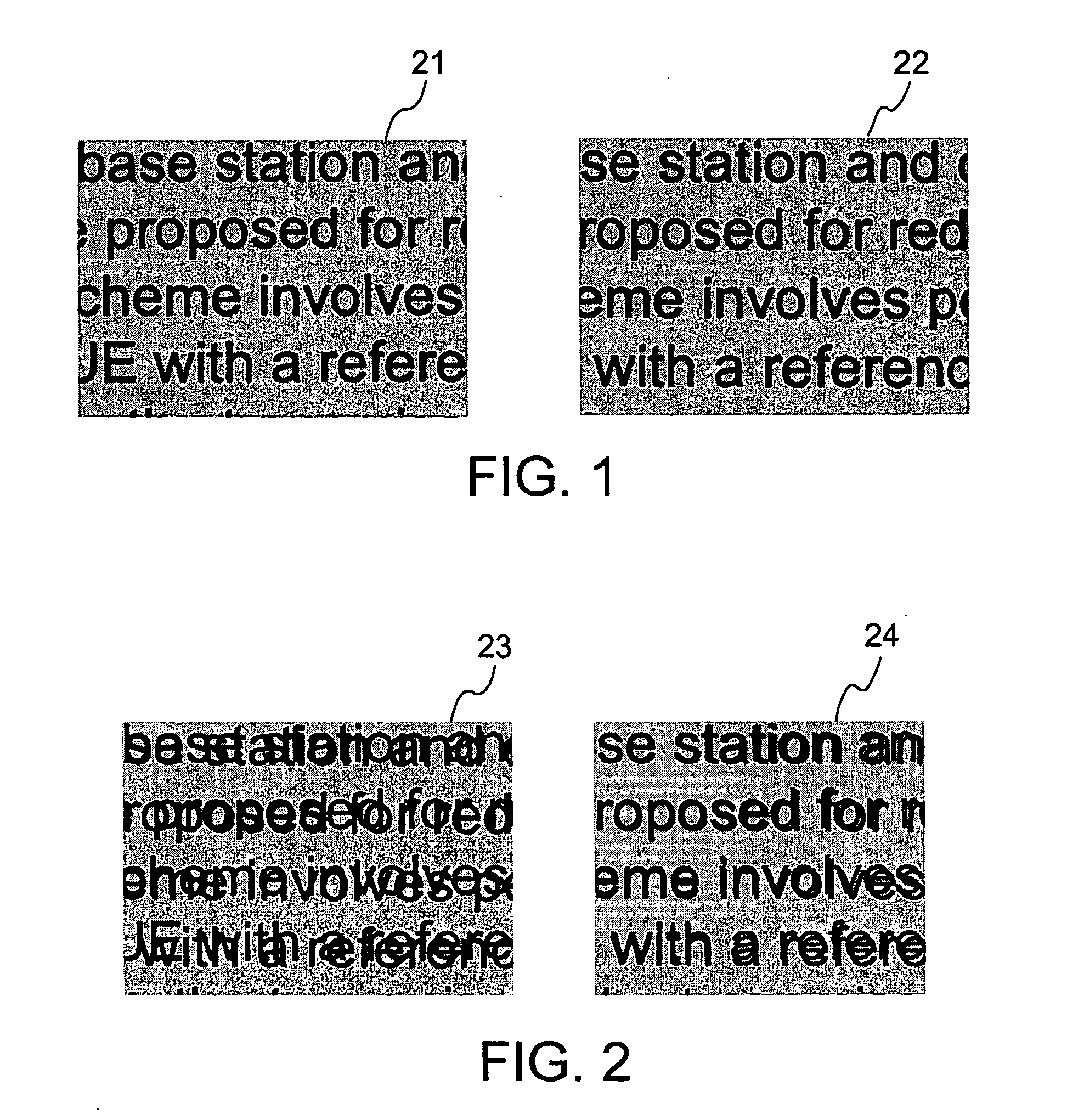
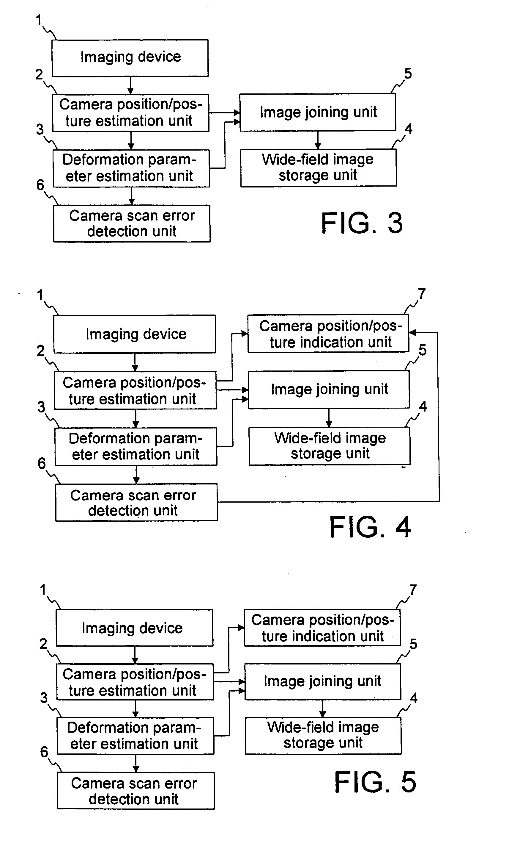
[0032]FIG. 3 shows a wide-field image input device according to the first embodiment of the present invention. The wide-field image input device joins a plurality of partial images obtained by imaging device 1, thereby generating a wide-field image. In the present embodiment, a user uses imaging device 1 to image a scene as an object by manually scanning imaging device 1. Imaging device 1 continuously images the object at a desired angle of field, a desired position, and a desired posture and obtains a partial image series including a series of digitized partial images. Imaging device 1 is embodied by, for example, a camera, in particular, by an imaging unit in the camera.

[0033] The wide-field image input device is provided with camera position / posture estimation unit 2, deformation parameter estimation unit 3, wide-field image storage unit 4, image joining unit 5, and camera scan error detection unit 6. Camera position / posture estimation unit 2 receives the digiti...

Example

Second Embodiment

[0053]FIG. 4 shows a wide-field image input device according to the second embodiment of the present invention. The wide-field image input device shown in FIG. 4 is configured by adding camera position / posture indication unit 7 to the wide-field image input device according to the first embodiment. Camera position / posture indication unit 7 receives the camera scan error signal from camera scan error detection unit 6 and the camera position / posture information from camera position / posture estimation unit 2. Preferably, the camera scan error signal is camera scan error information including information which scan error occurs.

[0054] Camera position / posture indication unit 7 performs one or more of the following four processes (a) to (d) of:

[0055] (a) visually indicating the change in the relative position between the camera and the imaging object or the change in the camera posture, or the change in the relative position and the change in the camera posture;

[0056]...

Example

Third Embodiment

[0067]FIG. 10 shows a wide-field image input device according to the third embodiment of the present invention. This wide-field image input device is configured by adding absolute distance acquirement unit 8 to the wide-field image input device according to the first or second embodiment. Absolute distance acquirement unit 8 measures the distance between the camera and the object and outputs distance information showing the measured distance to camera scan error detection unit 6. Absolute distance acquirement unit 8 like this is embodied by, for example, a distance sensor which is able to measure the distance between the camera and the object. The configuration shown in FIG. 10 is that absolute distance acquirement unit 8 is added to the wide-field image input device according to the second embodiment, however, absolute distance acquirement unit 8 may be added to the wide-field image input device according to the first embodiment shown in FIG. 3.

[0068] Also, accord...


PUM


Abstract

A wide-field image input device that joins a series of partial images obtained by continuously imaging an imaging object by an imaging device while the imaging device is manually scanned by a user, thereby generating a wide-field image, includes: a camera position/posture estimation unit for receiving a partial image series and calculating a change state of three-dimensional position and posture of the imaging device as time-series camera position/posture information; a deformation parameter estimation unit for calculating a geometrical deformation parameter between adjacent partial images from the camera position/posture information; an image joining unit for joining the partial images by using the geometrical deformation parameter so as to generate a wide-field image; and a camera scan error detection unit for detecting motion of the imaging device according to the camera position/posture information and outputting a camera scan error detection signal when an error is detected.

Description

TECHNICAL FIELD [0001] The present invention relates to a wide-field image input method and device for jointing a plurality of images that are taken, in order to generate a wide-field image, when the number of pixels and the angle of view in an imaging apparatus are smaller than those that are originally required. BACKGROUND ART [0002] When a paper surface, such as magazines, newspapers, and books, is imaged by an imaging device, e.g. camera, there is a case where the number of pixels in an image pickup element device is insufficient to image a desired range on the paper surface in a desired resolution. In this case, it is proposed that the camera images an object while scanning the object as licking and a plurality of frame images that are taken are jointed, thereby generating a wide-field image in high resolution. [0003] Japanese Patent Laid-Open Application No. 11-298837 (JP, 11-298837A) proposes an image input device used in a case where images (partial images) of adjacent scene...

Claims


Application Information

Patent Timeline
IPC IPC(8): G06K9/36
CPCG06T3/4038H04N1/195H04N1/19594H04N1/3876H04N2201/04743H04N5/2625H04N5/2628H04N2201/0414H04N2201/04739H04N5/2624
Inventor NAKAJIMA, NOBORUIKETANI, AKIHIKO
Owner NEC CORP
Why Eureka
Try Eureka