Power unit and image forming system

a technology of power unit and image, which is applied in the direction of switch power arrangement, contact mechanism, instruments, etc., can solve the problems of enlarging the output transformer of the dcps, increasing the cost, and enlarging the apparatus

Inactive Publication Date: 2008-02-07
KONICA MINOLTA BUSINESS TECH INC
View PDF1 Cites 8 Cited by
  • Summary
  • Abstract
  • Description
  • Claims
  • Application Information

AI Technical Summary

Benefits of technology

[0017]One aspect of the invention is a power unit including a main power source and an auxiliary power source having an electric double layer capacitor, wherein the power unit supplies power to a load and the power supplied to the load is shared by the main power source and the auxiliary power source, the power unit comprising: an output detection section for detecting an output of the auxiliary power source; and a power control section adapted to control an output current of the main power source based on a detection output of the output detection section.
[0018]Another aspect of the invention is a power unit including a main power source and an auxiliary power source having an electric double layer capacitor, wherein the power unit supplies power to a load and the power supplied to the load is shared by the main power source and the auxiliary power source, the power unit comprising: a current detection section for detecting an output current of the au...

Problems solved by technology

However, for that purpose, it causes enlargement of the apparatus such as enlarging the output transformer of the DCPS and an increase in cost.
However, in such a constitution that the internal impedance of the capacitor used as an auxiliary power source is higher than the internal impedance of the main power source, the capacitor cannot function sufficiently as an auxiliary power source.
When the internal impedance of the auxiliary power source becomes higher than the internal impedance of the main power source like this, at time of the peak load cur...

Method used


Image

  • Power unit and image forming system
  • Power unit and image forming system
  • Power unit and image forming system

Examples


Embodiment Construction

[0027]Hereinafter, the embodiment of the present invention will be explained.

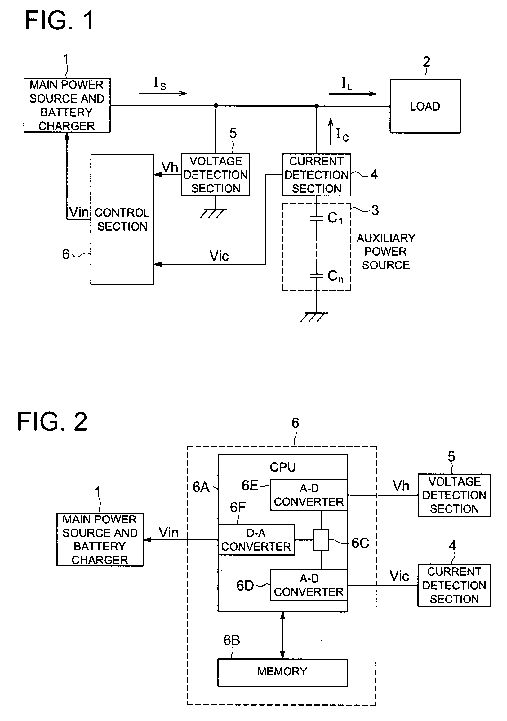
[0028]FIG. 1 is a schematic block diagram of the present invention.

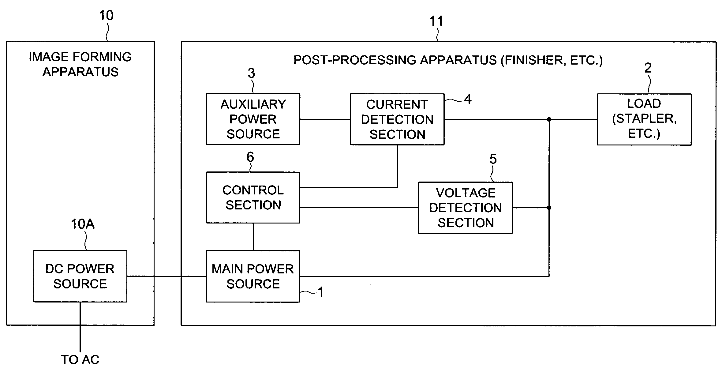
[0029]Numeral 1 indicates a main power source and concurrently charger (hereinafter, referred to as a main power source), which is composed of an AC-DC converter, or a DC-DC converter, or a storage battery.

[0030]Numeral 2 indicates a load, which is supplied with power from the main power source 1 and is driven.

[0031]Numeral 3 indicates an auxiliary power source, which is composed of a plurality of capacitors C1 to Cn connected in series and assists power supply from the main power source 1 to the load 2.

[0032]The main power source 1 and load 2 are connected directly to each other and the auxiliary power source 3, via a current detection section 4 for detecting the current supplied from the auxiliary power source, is connected to the connection route between the main power source 1 and the load 2. Further, between the connection route of the ...


PUM


Abstract

Present invention uses the main power source and auxiliary power source to supply power to a load, makes them take partial charge of power supply, and when the load current reaches its peak, detects a current and a voltage generated by the auxiliary power source, and when the detected values are larger than set values or lower than the set values, controls the output current of the main power source.

Description

[0001]This application is based on Japanese Patent Application No. 2006-212332 filed on Aug. 3, 2006, in Japanese Patent Office, the entire content of which is hereby incorporated by reference.BACKGROUND[0002]1. Technical Field[0003]The present invention relates to a power unit having a main power source and an auxiliary power source, particularly using an electric double layer capacitor as an auxiliary power source and an image forming system.[0004]2. Description of the Related Art[0005]When supplying all power to a load having a peak from a main power source such as a battery or a DCPS (DC power supply system), it is necessary to fit the power supply capacity of the main power source to the peak. However, for that purpose, it causes enlargement of the apparatus such as enlarging the output transformer of the DCPS and an increase in cost.[0006]On the other hand, to solve the aforementioned problem, a method for using a combination of an auxiliary power source using an electric doub...

Claims


Application Information

Patent Timeline
IPC IPC(8): G03G15/00G05F1/70
CPCG03G15/5004G03G2215/00983G03G2215/00789
Inventor WATANABE, HIROYUKIOKUTOMI, RYUJIYAMANE, HIDEOSASAMOTO, YOSHIHITO
Owner KONICA MINOLTA BUSINESS TECH INC
Why Eureka
Try Eureka