Platforms, apparatuses, systems and methods for processing and analyzing substrates

a substrate and platform technology, applied in the field of platforms, apparatuses, systems and methods for processing and analyzing substrates, can solve the problems of large equipment volume, large equipment volume, and difficult transportation, and achieve the effects of reducing machine weight, reducing physical size, and reducing the movement of glass. robust and/or compa

Active Publication Date: 2008-02-07
MICRONIC LASER SYST AB
View PDF37 Cites 88 Cited by
  • Summary
  • Abstract
  • Description
  • Claims
  • Application Information

AI Technical Summary

Benefits of technology

[0006] Example embodiments of the present invention provide devices and methods for using larger glass sizes. In at least one example embodiment, the glass may be rolled into a cylinder, thereby reducing the physical size by a factor of 3 in one dimension. Example embodiments of the present invention may have a cylindrical shape, which may allow a more robust and / or compact movement of the glass, reduced machine weight. Example embodiments of the present invention utilize relatively thin glass (e.g., about 0.7 mm, 0.62 mm and / or 0.5 mm thick). Thinner glass may be more flexible, and may be rolled onto a cylinder with a diameter of about 1 meter.

Problems solved by technology

Conventionally, the larger the screen size being manufactured, the more difficult the placement of the screens and the larger the area loss.
Conventional production technology is limited to about 2.5 times 3 meters.
If the glass is any larger the equipment must be very large, very heavy and difficult to transport.
Related art larger class machines for manufacturing display screens and solar panels have two types of problems: machine size and mechanical overhead.
The large size of equipment makes it very heavy, expensive, and difficult to transport.
The combination of larger mass and higher speed increases the mechanical overhead because of acceleration and deceleration times.

Method used


Image

  • Platforms, apparatuses, systems and methods for processing and analyzing substrates
  • Platforms, apparatuses, systems and methods for processing and analyzing substrates
  • Platforms, apparatuses, systems and methods for processing and analyzing substrates

Examples


Embodiment Construction

[0120] Example embodiments of the present invention provide a platform for processing larger substrates. A platform, according to at least one example embodiment of the present invention, may have a lower mass, smaller mechanical overhead and / or be more easily integrated with a variety of process tools.

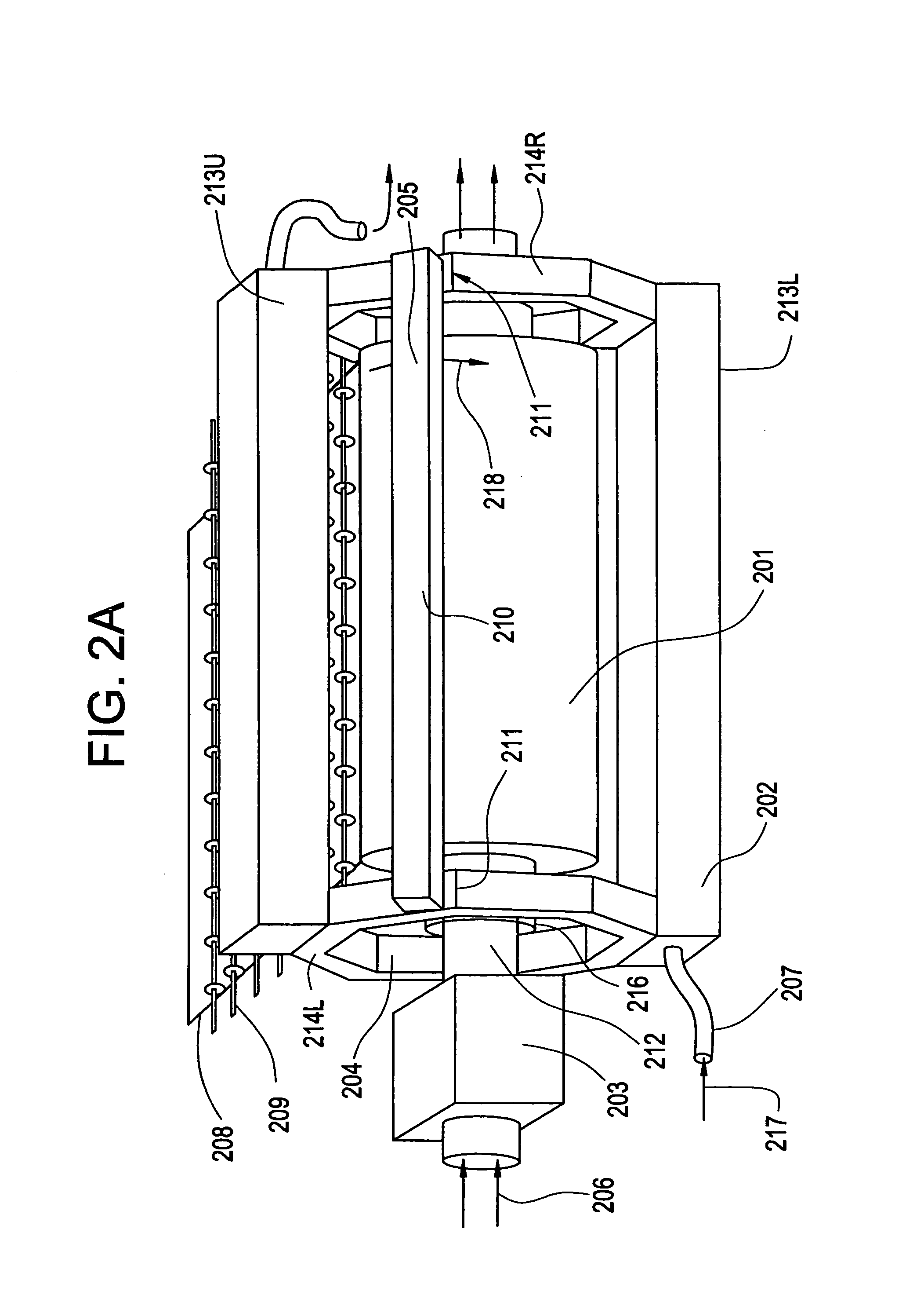
[0121]FIG. 2A illustrates a platform, according to an example embodiment. The platform of FIG. 2A may include a frame 202. The frame 202 may include upper and lower supporting structures 213U and 213L and end support structures 214L and 214R. The support structures 213U, 213L, 214L and 214R may be formed, for example, of a continuous piece of metallic material (e.g., sheet metal), and may include a tube 207 formed therein for temperature control. The temperature of the support structures 213U, 213L, 214L and 214R may be controlled by flowing fluid (e.g., air, liquid, gas, etc.) through the tube 207 in direction 217. Alternatively, the support structures 213U, 213L, 214L and 214R may ...


PUM

PropertyMeasurementUnit
thickaaaaaaaaaa
sizesaaaaaaaaaa
thickaaaaaaaaaa

Abstract

Devices and methods for manufacturing displays, solar panels and other devices using larger size workpieces are provided. The workpiece is rolled into a cylinder, thereby reducing the physical size by a factor of 3 in one dimension. The stages on which the workpieces are rolled have a cylindrical shape, which allows a more robust and/or compact movement of the glass, reduced machine weight. The workpieces are relatively thin, more flexible, and are rolled onto a cylinder with a diameter of about 1 meter.

Description

PRIORITY STATEMENT [0001] This non-provisional U.S. patent application claims priority under 35 U.S.C. § 119(e) to U.S. provisional patent application Ser. No. 60 / 776,919, filed on Feb. 28, 2006, and is a continuation-in-part of non-provisional U.S. patent application Ser. No. 11 / 586,612, filed on Oct. 26, 2006, and non-provisional U.S. patent application Ser. No. 11 / 586,614, filed on Oct. 26, 2006, each of which claim priority under 35 U.S.C. § 119(e) to U.S. provisional patent application Ser. Nos. 60 / 730,009, filed on Oct. 26, 2005 and 60 / 776,919, filed on Feb. 28, 2006. The entire contents of all of these documents are incorporated herein by reference.BACKGROUND Description of the Conventional Art [0002] Conventional flat panel televisions (TVs) are replacing conventional cathode ray tube televisions (CRT TVs). Conventional manufacturing methodologies utilize larger glass sizes of approximately 2×2.5 meters. The larger size glass may allow more freedom to place screens of differ...

Claims


Application Information

Patent Timeline
Patent Type & Authority Applications(United States)
IPC IPC(8): B05C5/00B23P19/00B23Q17/00B23Q7/00B25B27/14C23C14/28B05C11/00B21D53/10
CPCG03F7/70391G03F7/704Y10T29/497Y10T29/4976Y10T29/53961Y10T29/534Y10T29/49998
Inventor STIBLERT, LARSSANDSTROM, TORBJORNLUBEREK, JAREKLOCK, TOMAS
Owner MICRONIC LASER SYST AB
Why Eureka
Try Eureka