Damping element and device for stabilization of adjacent vertebral bodies

a technology of adjacent vertebrae and adamant element, which is applied in the direction of prosthesis, osteosynthesis device, wound spring, etc., can solve the problems of complexity, time loss, and inconvenient design of surgeons, and achieve the effect of reducing the cost of surgery, improving the quality of care, and improving the quality of li

Inactive Publication Date: 2008-02-07
SYNTHES USA
View PDF45 Cites 110 Cited by
  • Summary
  • Abstract
  • Description
  • Claims
  • Application Information

AI Technical Summary

Benefits of technology

[0032] Pedicle screws or pedicle hooks that are fitted with receiving means allowing concurrent connection between two parallel, longitudinal affixation elements and the pedicle screw or pedicle hook are known for instance from U.S. Pat. No. 4,653,481 (Howland). Similarly to the longitudinal supports cited in said patent, the damping elements of the present invention may be affixed by means of bars mounted on the connectors parallel to the longitudinal axis for instance in parallel ducts to the screw heads. Very easily and without further manipulation, the damping element displaceability in the ducts parallel to the longitudinal axis allows inserting a damping element of the present invention—which was prestressed to a desired spring force before implantation—into the receiving means at the pedicle screws. The compensation in length at different spacings between the pedicle screws or pedicle hooks is implemented by the axial d

Problems solved by technology

While the length of the spiral springs is adjustable, this design only allows a change in the spring force between two adjacent pedicle screws and hence between two adjacent vertebrae.
This device entails the drawback that only compressive forces between the pedicle screws may be absorbed.
Such a design is awkward and entails storing a significant number of damping elements of different lengths.
In the first place the plastic band

Method used


Image

  • Damping element and device for stabilization of adjacent vertebral bodies
  • Damping element and device for stabilization of adjacent vertebral bodies
  • Damping element and device for stabilization of adjacent vertebral bodies

Examples


Embodiment Construction

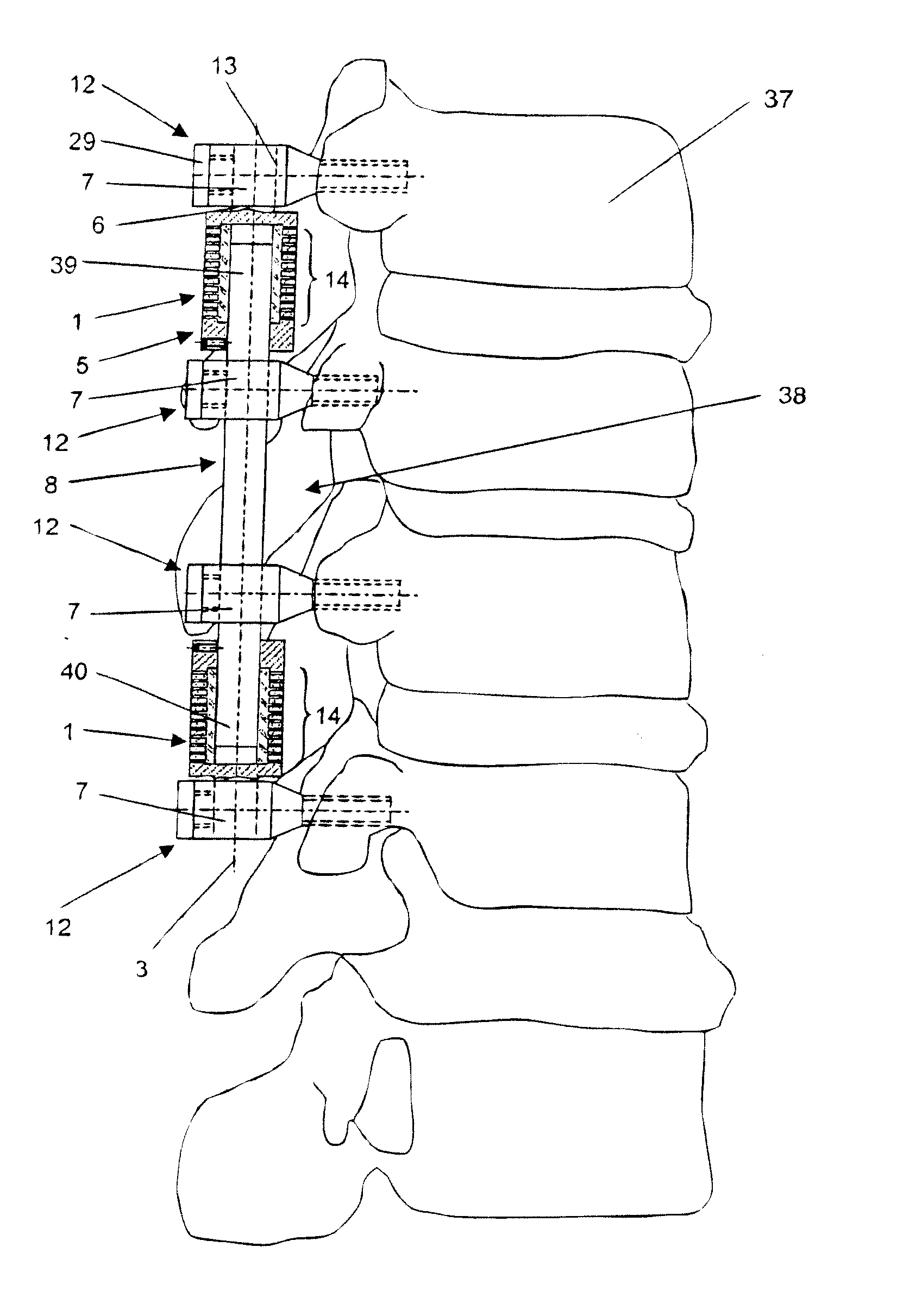
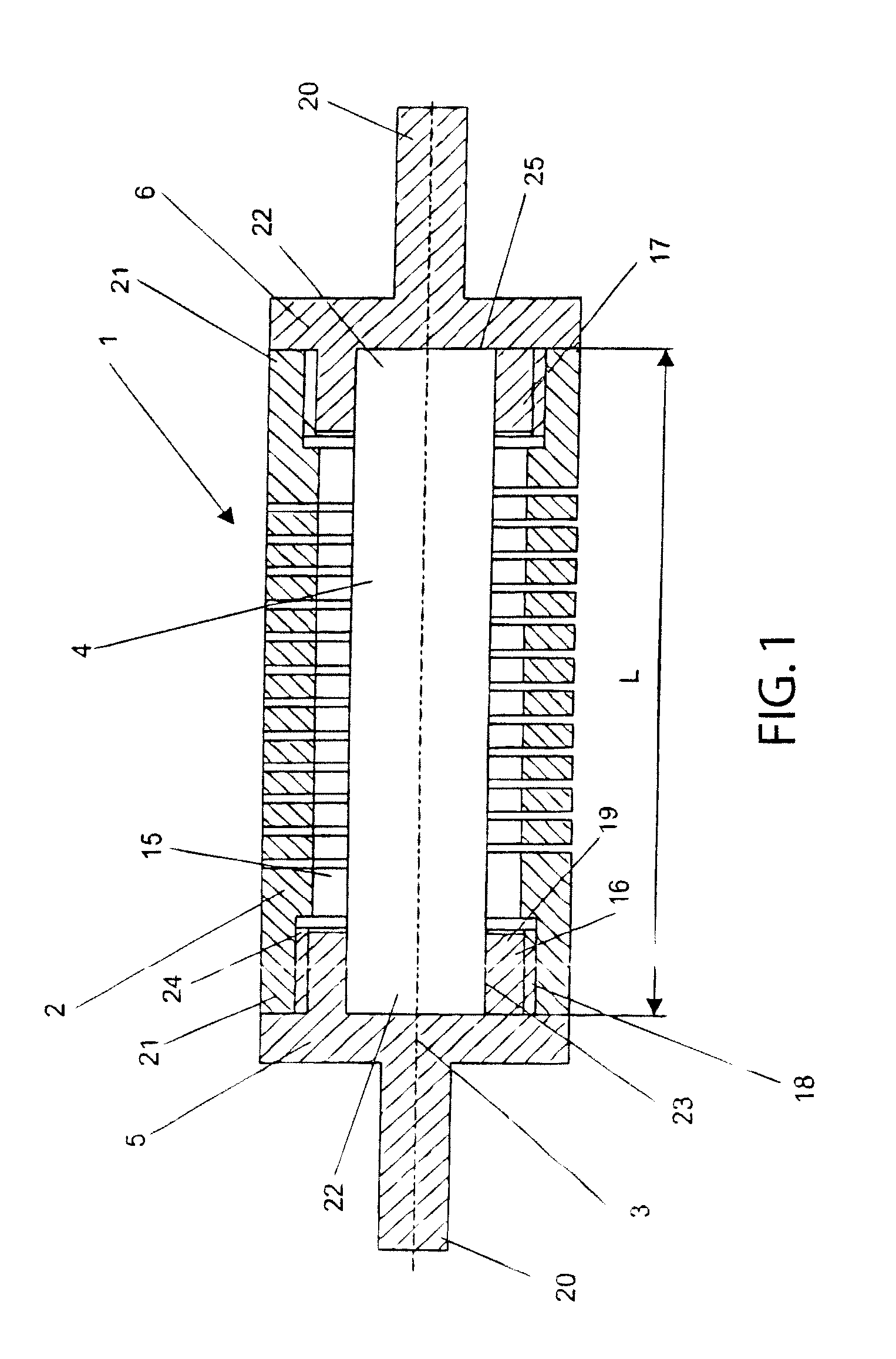
[0047]FIG. 1 shows an embodiment mode of the damping element 1 of the invention having two spring elements 2, 4 concentrically mounted with the longitudinal axis 3. The first spring element 2 is designed as a helical spring with a central cavity 15, whereas the second spring element 4 is bar-shaped and configured in said cavity 15. The end-side connectors 5, 6 also are mounted coaxially with the longitudinal axis 3 and each is fitted with a threaded segment 16, 17 with an outer thread 18, said segments being coaxial with the longitudinal axis 3 and pointing toward the spring elements 2, 4. The first spring element 2 is fitted at its axial ends 21 with inner threads 24 in the cavity 15 which match the outer threads 18, as a result of which the threaded segments of the connectors 5, 6 can be screwed into the first spring element 2. Moreover each connector 5, 6 comprises an open recess 23 configured coaxially with the longitudinal axis 3 at the inner end 19 of said connector, as a resu...


PUM


Abstract

A damping element includes: two spring elements which are coaxial with or parallel to a longitudinal axis and two axially end-side connectors, where the first spring element exhibits a spring rate F, the second spring element exhibits a spring rate f, and the spring rates F and f are different. A device stabilizing adjacent vertebrae, including N pedicle screws or hooks, where N is greater than or equal to 3 and where each pedicle screw or pedicle hook includes a receiving device receiving a longitudinal affixation device and where an element acting as a spring is inserted between two adjacent pedicle screws or pedicle hooks.

Description

CROSS-REFERENCE TO RELATED APPLICATIONS [0001] This application is a continuation of U.S. patent application Ser. No. 10 / 497,794, now U.S. Pat. No. ______, which claimed the benefit of International Application No. PCT / CH02 / 00180, filed Mar. 28, 2002, which claims the benefit of International Application No. PCT / CH01 / 00705, filed Dec. 7, 2001. Priority is claimed to the applications listed above, which are incorporated herein by reference.BACKGROUND OF THE INVENTION [0002] The present invention relates to a damping element. [0003] The French patent document 2,799,949 A discloses a spinal fixing device consisting of a number of tulip-like pedicle screws which in lieu of the conventional rigid longitudinal support are connected to each other by spiral spring elements. While the length of the spiral springs is adjustable, this design only allows a change in the spring force between two adjacent pedicle screws and hence between two adjacent vertebrae. This document allows no conclusion ...

Claims


Application Information

Patent Timeline
IPC IPC(8): A61B17/58A61B17/56F16F3/02A61B17/70F16F1/12F16F3/10
CPCA61B17/7004F16F3/10F16F1/123A61B17/7028A61B17/70
Inventor STUDER, ARMINFRIGG, ROBERT
Owner SYNTHES USA
Why Eureka
Try Eureka