Prosthetic foot with variable medial/lateral stiffness

Active Publication Date: 2008-02-07
FREEDOM INNOVATIONS INC
View PDF99 Cites 25 Cited by
  • Summary
  • Abstract
  • Description
  • Claims
  • Application Information

AI Technical Summary

Benefits of technology

[0008]It has been recognized that it would be advantageous to develop a prosthetic foot with a variable stiffness foot plate for providing smooth and steady multi-axial rotation laterally across the forefoot region of the foot to allow the wearer to maneuver uneven terrain. Addition

Problems solved by technology

With respect to prosthetic feet, the development of a functional and natural artificial foot has been limited by material and imagination.
Few designs consider the lateral, or side to side rotation of the foot when the foot is use

Method used


Image

  • Prosthetic foot with variable medial/lateral stiffness
  • Prosthetic foot with variable medial/lateral stiffness
  • Prosthetic foot with variable medial/lateral stiffness

Examples


Embodiment Construction

[0020]Reference will now be made to the exemplary embodiments illustrated in the drawings, and specific language will be used herein to describe the same. It will nevertheless be understood that no limitation of the scope of the invention is thereby intended. Alterations and further modifications of the inventive features illustrated herein, and additional applications of the principles of the inventions as illustrated herein, which would occur to one skilled in the relevant art and having possession of this disclosure, are to be considered within the scope of the invention.

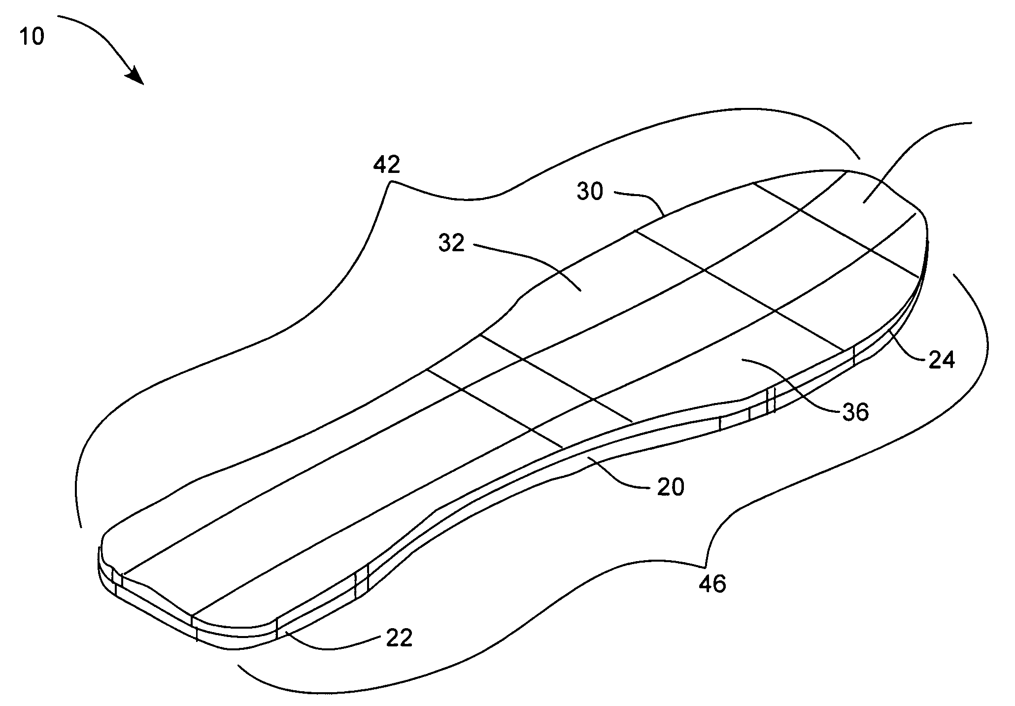
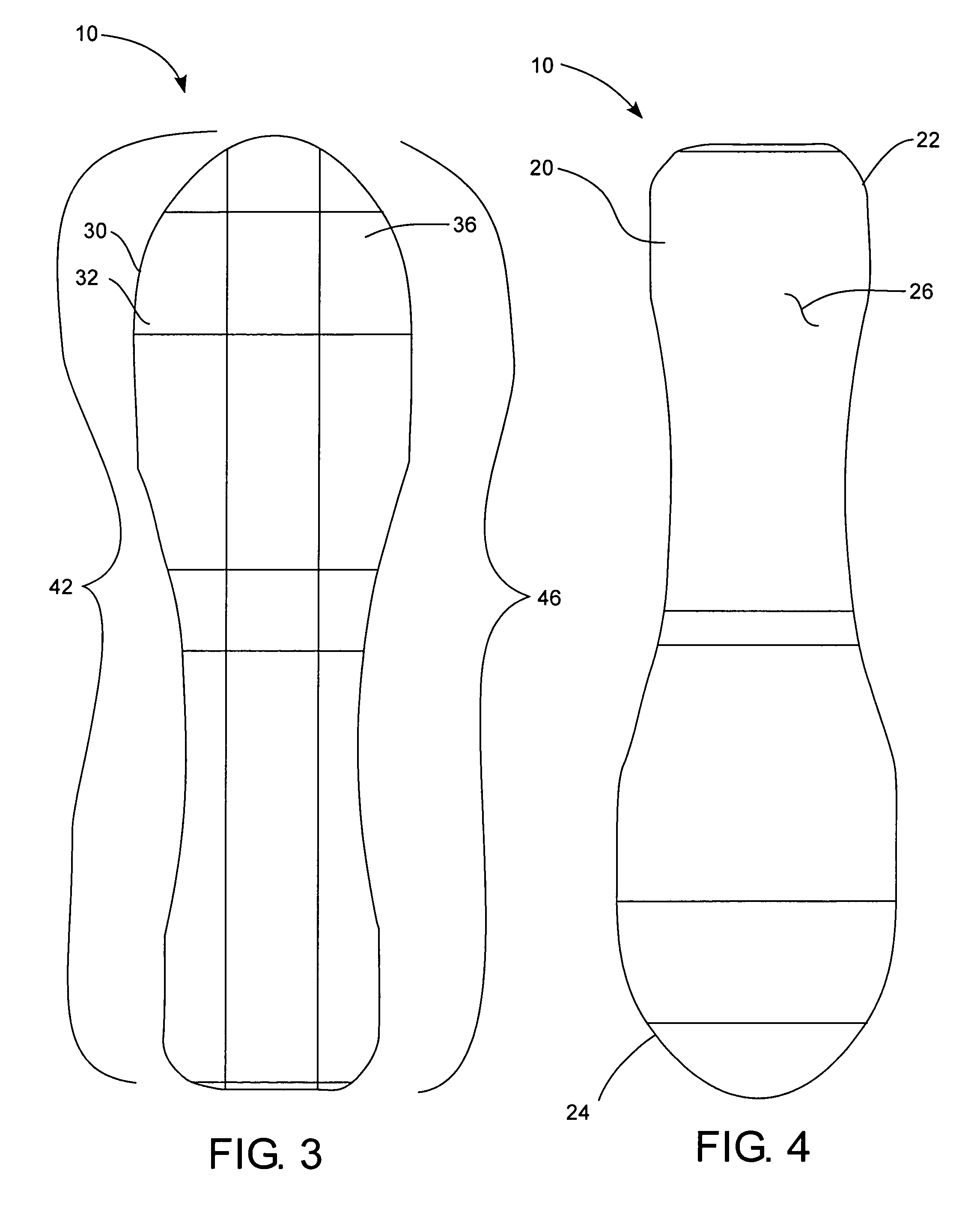
[0021]The present invention relates generally to a foot plate for a prosthetic foot. The foot plate can have a variable stiffness across a forefoot portion of the footplate to provide a smooth and steady multi-axial rotation laterally across the forefoot region of the foot to allow the wearer to maneuver uneven terrain. The foot plate can have a sole plate and a layer with laterally variable stiffness disposed ab...


PUM


Abstract

A foot plate for a prosthetic foot includes a sole plate and a layer with laterally variable stiffness disposed above the sole plate. The layer has a medial portion and a lateral portion. The lateral portion has a stiffness different than a stiffness of the medial portion, such as a greater stiffness to provide a relatively softer instep and a relatively stiffer out-step.

Description

BACKGROUND OF THE INVENTION[0001]1. Field of the Invention[0002]The present invention relates generally to a prosthetic foot with a variable stiffness sole plate.[0003]2. Related Art[0004]Many individuals have lost a limb for various reasons including war, accident, or disease. In most instances these individuals are not only able to live relatively normal lives, but physically active lives as well. Oftentimes, these individuals are aided in their everyday lives by a prosthetic limb. The objective of prosthesis is to provide an artificial limb that simulates the function and natural feel of the replaced limb.[0005]With respect to prosthetic feet, the development of a functional and natural artificial foot has been limited by material and imagination. Many designs have attempted to copy the anatomy of the foot or simulate its actions by replacing the bones and muscle with various mechanical simulation by replacing the entire foot with an energy storage element such as a spring. As th...

Claims


Application Information

Patent Timeline
IPC IPC(8): A61F2/66
CPCA61F2/66A61F2/76A61F2002/5056A61F2250/0018A61F2002/665A61F2002/6678A61F2002/6685A61F2002/6642
Inventor CHRISTENSEN, ROLAND J.
Owner FREEDOM INNOVATIONS INC
Why Eureka
Try Eureka