Wiper lever with a driven wiper arm and a wiper blade

a technology of wiper blade and wiper arm, which is applied in the direction of vehicle maintenance, vehicle cleaning, domestic applications, etc., can solve the problems of undesirable increase in air stream noise, inability to properly wipe the wiper arm, and negative pressure build up on the rear side, etc., and achieves a suitable pivot arrangement. , the effect of simpl

Inactive Publication Date: 2008-02-14
ROBERT BOSCH CORP
View PDF4 Cites 25 Cited by
  • Summary
  • Abstract
  • Description
  • Claims
  • Application Information

AI Technical Summary

Benefits of technology

[0005] Due to the arrangement of the cap in the connection area between the wiper arm and the wiper blade, an elegant transition between the two wind deflector strip sections adjacent to the connecting device can be achieved via an appropriate formation of the cap. In doing so, it is possible to adapt at least the cap sections, which can also cover the areas of these sections that are adjacent to them, to the shape of the wind deflector strip. Moreover, problem zones on the wiper lever that oppose a laminar flow of the air stream and generate air stream noise are thereby avoided. Finally, the cap protects the sensitive articulated connection between the wiper arm and the wiper blade against environmental influences such as dirt from the road, snow, ice, etc.
[0006] A particularly simple adaptation of the cap to the embodiment of the wiper blade is possible if the cap is supported by the wiper blade, in particular if it is locked to the wiper blade.
[0010] With respect to the flexibility of the wiper blade or the supporting element it can be particularly advantageous if, in the area of the holding claws of the coupling part serving as a connecting piece, the cap is provided, on its elastically deflectable inside wall, with clamp-like safety claws that grip over the holding claws.
[0012] Because the wind deflector strip material ages over the course of time, something that goes hand in hand with a certain shrinkage, an air gap can form between the cap and the front sides of the wind deflector strip partial sections that face it, which can lead to the already described disadvantages regarding the optical effect and the intensification of noise. This can be avoided in accordance with a development of the invention with extensions on the cap that cover the end areas of the wind deflector strip partial sections that face them.
[0013] For optical reasons and for reasons related to the undesired generation of air stream noise, it can be advantageous if the cap is provided with a flute on its one longitudinal wall in continuation of the flow fluting of the wind deflector strip.
[0017] A simple, suitable pivot arrangement is achieved for the cap if the cap is manufactured of an elastic plastic and the pivot pins are arranged on elastically deflectable wall areas of the cap.

Problems solved by technology

On the other hand, a considerable negative pressure builds up on the rear side facing away from the air stream due to the abovementioned wiper blade structure.
In the combined action of these two previously mentioned pressures, both of which are acting in the opposite direction of the wiper blade application force, they are at least reduced at higher travel speeds so that a proper wiper result is no longer possible.
In addition, this interruption of the flow surface on the wind deflector strip contributes to an undesirable increase in air stream noise due to the edges and gaps that are thereby produced.

Method used


Image

  • Wiper lever with a driven wiper arm and a wiper blade
  • Wiper lever with a driven wiper arm and a wiper blade
  • Wiper lever with a driven wiper arm and a wiper blade

Examples


Embodiment Construction

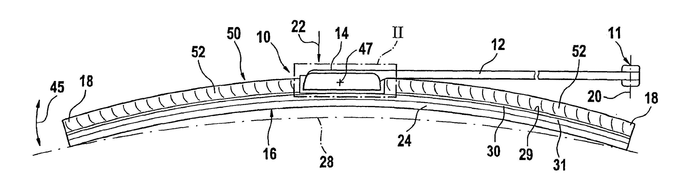
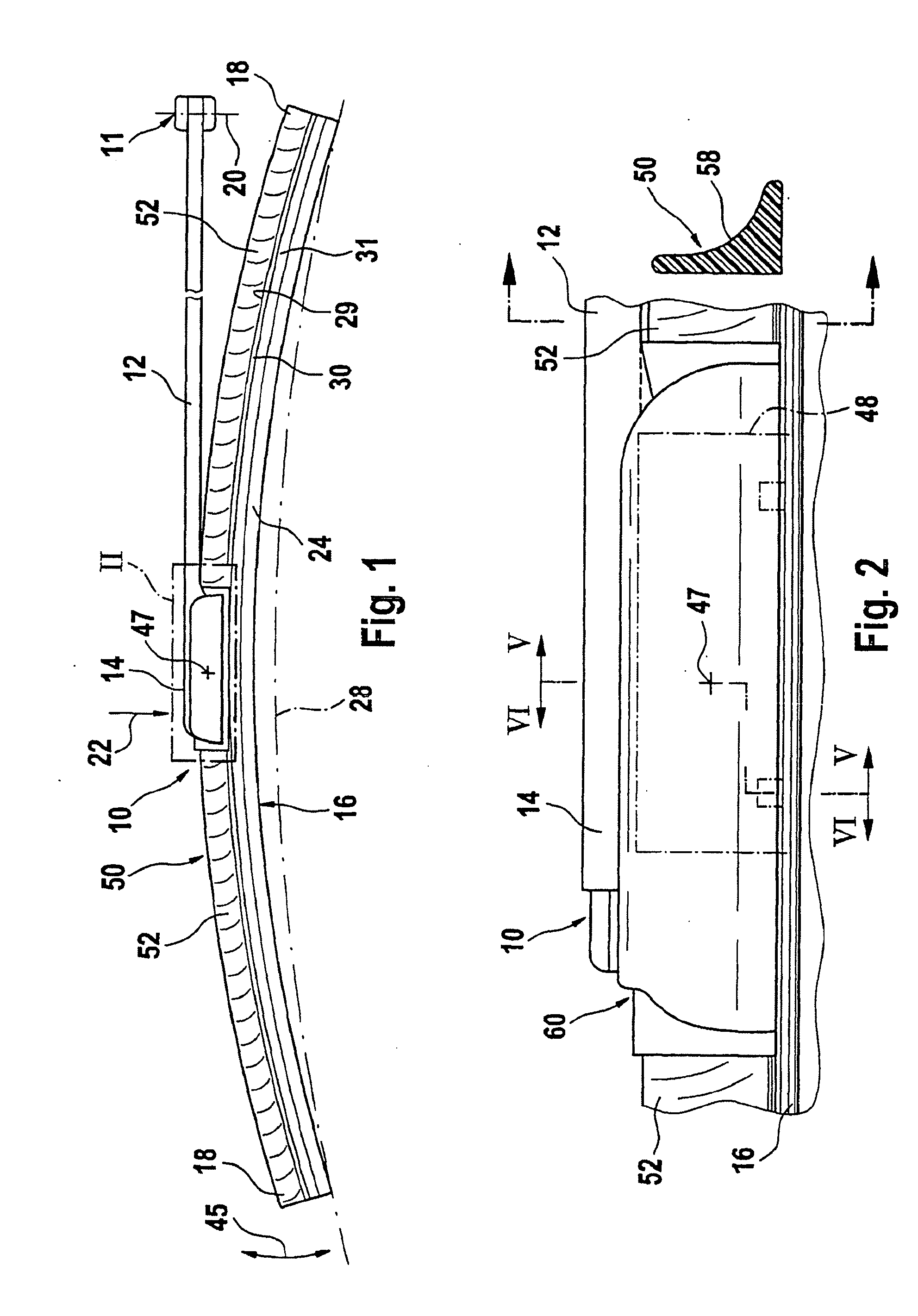
[0034] A first exemplary embodiment of a wiper lever 10 according to the invention (FIG. 1) includes a wiper arm 12 driven on one end and guided on a motor vehicle (not shown here). The driven end of the wiper arm has been assigned reference number 11 in FIG. 1. A long-stretched-out wiper blade 16 belonging to the wiper lever 10 is linked to the other, free end 14 of the wiper arm. The wiper arm 12 is positioned on its drive end 11 in such a way that it can move in a pendulum fashion between reverse positions around a pendulum axis 20 during wiper operation in a vertical plane on the drawing plane. In doing so, the wiper blade 16 is moved transverse to its longitudinal extension over the to-be-wiped window, whereby it is adjacent to the surface 28 of the to-be-wiped window with a rubber elastic wiper strip 24. The wiper strip 24 is connected parallel to its longitudinal axis with a band-like, long-stretched-out, elastic supporting element 30, on whose upper band surface 29 facing aw...


PUM


Abstract

Wiper lever (10) with a driven wiper arm (12) and a wiper blade (16) linked to it for cleaning windows, particularly those of motor vehicles, which is provided with a band-like, long-stretched-out, elastic supporting element (30), which features, on its lower band surface facing the window, a long-stretched-out, rubber elastic wiper strip (24) that can be applied to it, on whose upper band surface (29), particularly in the longitudinal middle area of the supporting element (30), a coupling part (32) is situated and wind deflector strip partial sections (52) extending to the ends of the supporting element are arranged on both sides of the coupling part (32). An especially harmonic transition between the wiper blade (16) and the wiper arm (12) is achieved in the area of the joint (46, 47) connecting these two wiper lever parts if the wiper lever (10) is provided with a cap (60) to cover the connection area between the wiper blade (16) and the wiper arm (12).

Description

RELATED APPLICATIONS [0001] This application is a continuation of U.S. application Ser. No. 10 / 416,842, filed May 16, 2003, which is a national stage filing under 35 U.S.C. 371 of International Application No. PCT / DE01 / 04307, filed Nov. 16, 2001, which claims priority to German Application No. 10057253.7, filed Nov. 18, 2000, the entire contents of which are incorporated herein by reference.BACKGROUND OF THE INVENTION [0002] In the case of a wiper lever of the type designated in the pre-characterizing clause of the independent claim, the supporting element of the wiper blade is supposed to guarantee, over the entire wiper field being covered by the wiper blade, the most uniform possible distribution of wiper blade application force on the window originating from the wiper arm. Due to the corresponding curvature of the relaxed supporting element—i.e., when the wiper blade is not adjacent to the window—the ends of the wiper strip that are placed completely against the window during wi...

Claims


Application Information

Patent Timeline
Patent Type & Authority Applications(United States)
IPC IPC(8): B60S1/38B60S1/40B60S1/34B60S1/32
CPCB60S1/3806B60S1/3856B60S1/3863B60S1/3868B60S2001/4061B60S1/40B60S1/4064B60S2001/382B60S2001/3843B60S1/3879
Inventor BREESCH, FRANS
Owner ROBERT BOSCH CORP
Why Eureka
Try Eureka