Clutched super turbo control strategy

a super turbo and control strategy technology, applied in the direction of engine controllers, machines/engines, engine components, etc., can solve the problems of reducing the durability of the clutch, objectionable supercharger engagement, and undesirable nvh condition

Inactive Publication Date: 2008-02-14
EATON INTELLIGENT POWER LTD
View PDF4 Cites 18 Cited by
  • Summary
  • Abstract
  • Description
  • Claims
  • Application Information

AI Technical Summary

Benefits of technology

[0008]It is a more specific object of the present invention to provide such an improved method of controlling an internal combustion engine superturbo boosting system which has the ability to substantially reduce the speed differential between the supercharger clutch and the input to the supercharger, at the time of clutch engagement, thus reducing the undesirable results of sudden clutch engagement.
[0009]It is an even more specific object of the present invention to provide such an improved method of controlling an internal combustion engine superturbo boosting system, which achieves the above-stated objects without the need for additional complex and expensive structure, or complex control schemes.

Problems solved by technology

Second, it has been observed that supercharger engagement can be objectionably harsh due to the sudden and large change in speed of the supercharger (high angular acceleration) as the supercharger clutch is engaged, especially at the lower end of the load range and the higher end of the speed range where the supercharger is operational.
Furthermore, when the supercharger clutch is disengaged (e.g., at engine speeds above about 3,500 rpm or below 3,500 rpm when the demanded load is low enough to be covered solely by the turbocharger), and then engine speed drops, and thereafter it is desired to again operate the supercharger, the re-engagement of the supercharger clutch (for example, with the supercharger input stationary, and the clutch turning 2,500 rpm) would typically occur in a sudden manner likely to result, over time, in reduced durability of the clutch, and observed to cause an undesirable NVH condition.

Method used


Image

  • Clutched super turbo control strategy
  • Clutched super turbo control strategy
  • Clutched super turbo control strategy

Examples


Embodiment Construction

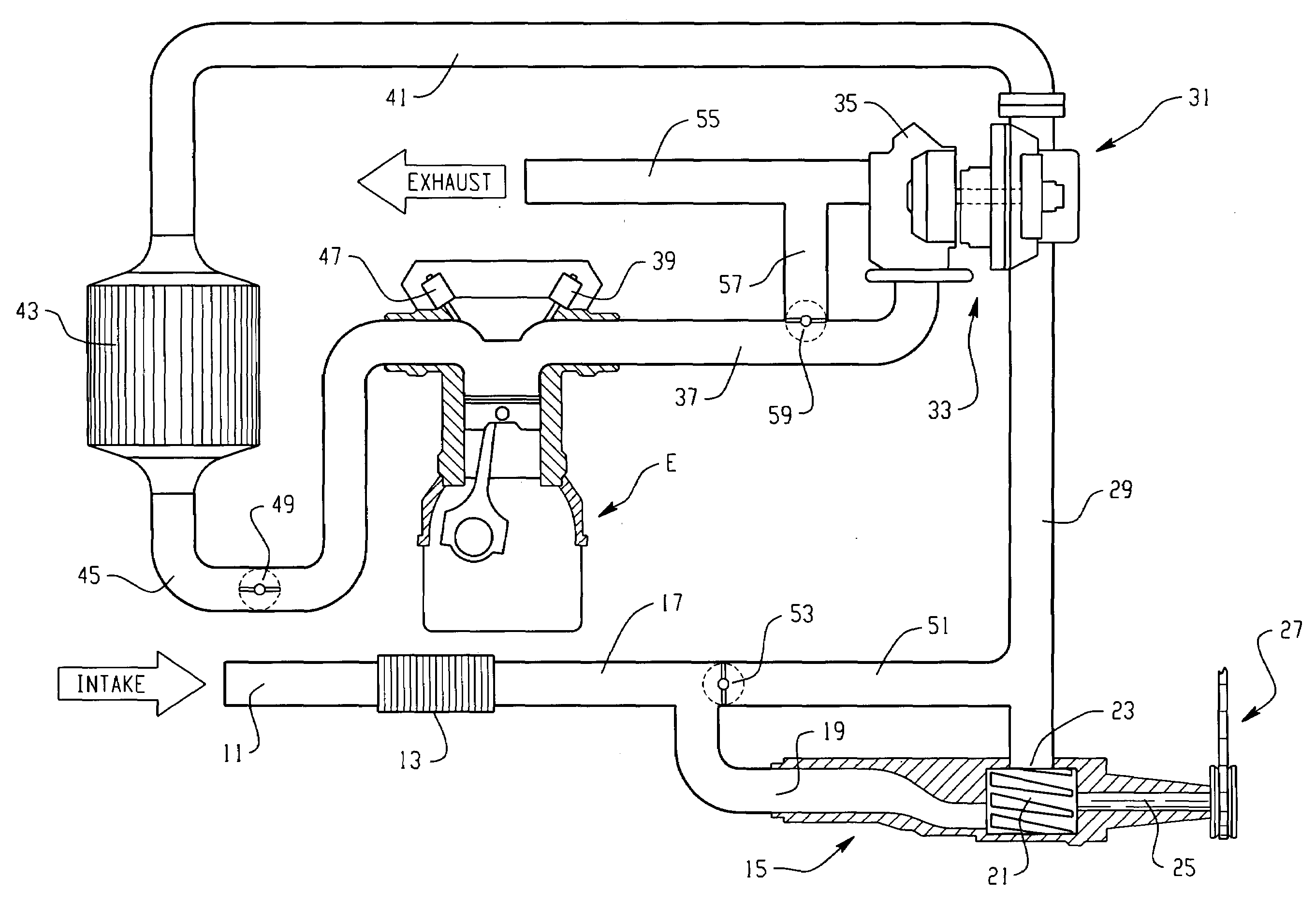
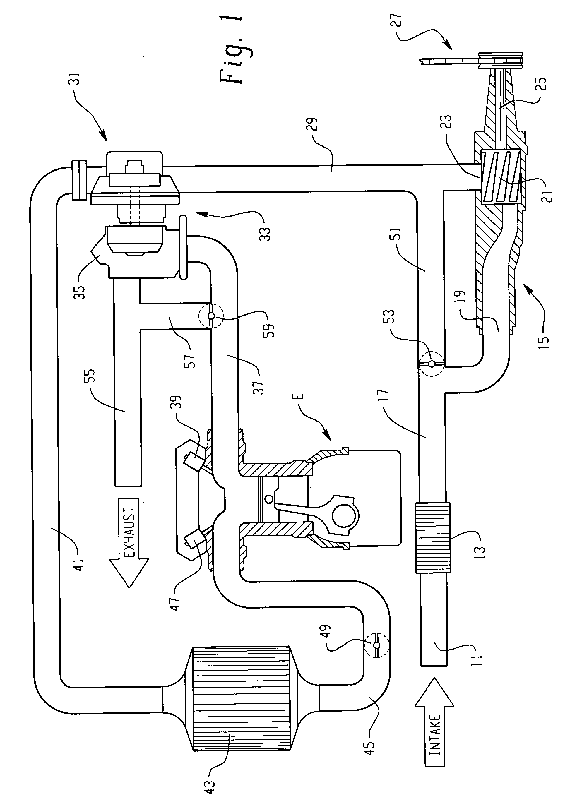
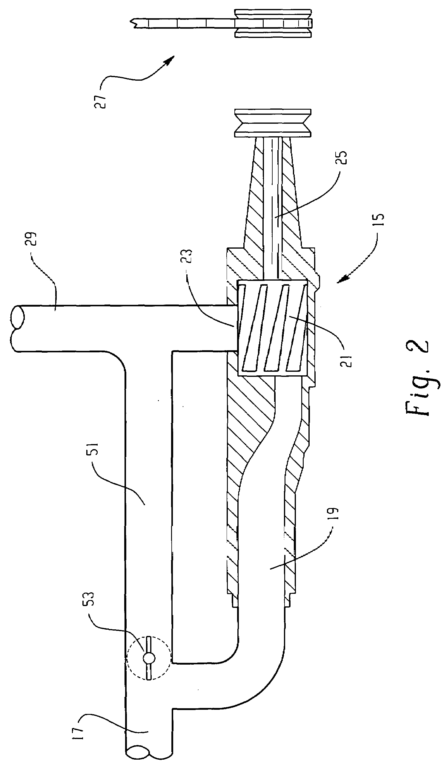
[0017]Referring now to the drawings, which are not intended to limit the invention, FIG. 1 illustrates a vehicle internal combustion engine, including a “superturbo” boosting system, as that term has been generally defined, and as will be described in greater detail subsequently. Included is a conventional vehicle engine, generally designated E, and represented herein, for simplicity, by a single cylinder-piston combination. Charge air, to be fed into the combustion chamber of the engine E, enters through an intake 11 (see arrow), then flows through an air filter 13, and then flows to a supercharger, generally designated 15, through an air duct 17 which communicates the incoming air into an inlet 19 of the supercharger.

[0018]The supercharger 15 also has, typically, a set of rotors 21 which transport volumes of the incoming air from the inlet 19 of the supercharger 15 to an outlet 23, whenever the supercharger is receiving mechanical drive to its input, represented somewhat schematic...


PUM


Abstract

A method of controlling an internal combustion engine boosting system of the type including an exhaust-driven turbocharger and a mechanically-driven supercharger. The supercharger includes rotors and a clutch operable in a first condition to transmit torque from a mechanical drive source to a supercharger input in response to a positive input, and operable in a second condition to interrupt the transmission of torque from the source to the input. The method is characterized by determining possible operation of the clutch in a first condition; and commanding a bypass valve toward a closed position, forcing air through the supercharger. The airflow causes the supercharger rotors to rotate, thus rotating the input of the supercharger prior to the clutch operating in the first condition.

Description

BACKGROUND OF THE DISCLOSURE[0001]The present invention relates to vehicle engine charging systems, and more particularly, to such systems of the type including both a mechanically-driven supercharger (such as a Roots type blower), and an exhaust gas-driven turbocharger. Vehicle engine charging systems of this type are sometimes referred to, for simplicity, by the term “superturbo”.[0002]As is well known to those skilled in the art of vehicle engine boosting, there are two primary types of boosting devices typically used to boost the air pressure in the combustion chamber of internal combustion engines. The first is typically referred to as a “supercharger” (although that term is sometimes used generically for all boosting devices), and for purposes of the present specification, the term “supercharger” will be understood to mean and include a mechanically-driven charging (air pumping) device, i.e., the supercharger is driven at a speed which is normally proportional to engine speed....

Claims


Application Information

Patent Timeline
Patent Type & Authority Applications(United States)
IPC IPC(8): F02B29/04F02B33/44
CPCF02B33/32F02B33/38F02B37/04Y02T10/144F02B39/12F02D2009/0283F02B37/16Y02T10/12
Inventor JORGENSEN, RORY E.
Owner EATON INTELLIGENT POWER LTD
Why Eureka
Try Eureka