Method and Apparatus for Determining Flow Pressure Using Density Information

a density information and flow pressure technology, applied in the field of flow meters, can solve problems such as inability to use an average pressure value to induce unacceptable errors

Active Publication Date: 2008-02-14
MICRO MOTION INC
View PDF6 Cites 53 Cited by
  • Summary
  • Abstract
  • Description
  • Claims
  • Application Information

AI Technical Summary

Benefits of technology

[0056] Preferably, the method further comprises where the pressure of the flowing material is used to correct a pressure effect in the mass flow rate measured by the Coriolis flow meter.

Problems solved by technology

Using an average pressure value can induce unacceptable errors when there are large variations in the operating pressure in the system.

Method used


Image

  • Method and Apparatus for Determining Flow Pressure Using Density Information
  • Method and Apparatus for Determining Flow Pressure Using Density Information
  • Method and Apparatus for Determining Flow Pressure Using Density Information

Examples


Embodiment Construction

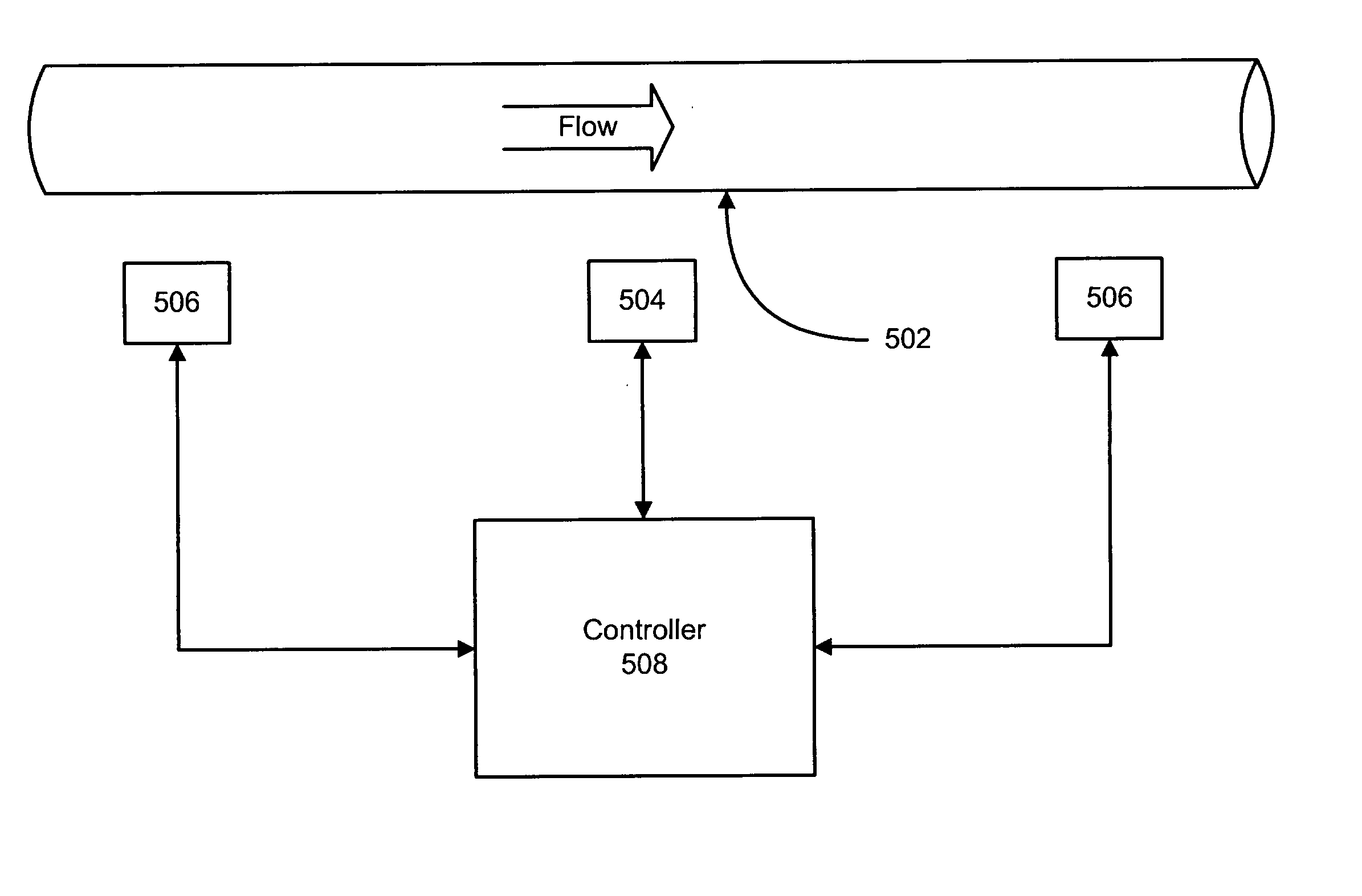
[0072]FIGS. 1-9 and the following description depict specific examples to teach those skilled in the art how to make and use the best mode of the invention. For the purpose of teaching inventive principles, some conventional aspects have been simplified or omitted. Those skilled in the art will appreciate variations from these examples that fall within the scope of the invention. Those skilled in the art will appreciate that the features described below can be combined in various ways to form multiple variations of the invention. As a result, the invention is not limited to the specific examples described below, but only by the claims and their equivalents.

[0073] Flowing density of a gas is expressed by the non-ideal gas law and is: ρ=PMZRT(1)

Where ρ is the density of the flowing gas, P is the pressure of the flowing gas, M is the molar weight of the gas, Z is the compressibility of the gas, R is the gas constant, and T is the temperature of the flowing gas. In many cases the tem...


PUM

PropertyMeasurementUnit
densityaaaaaaaaaa
Coriolis flow meteraaaaaaaaaa
pressureaaaaaaaaaa

Abstract

A method and apparatus is disclosed that determines the density of a material flowing through a Coriolis flow meter The density is used to infer the pressure of the flowing material. The inferred pressure may be used to correct for the secondary pressure effect in the Coriolis flow meter or may be reported to an external device.

Description

BACKGROUND OF THE INVENTION [0001] 1. Field of the Invention [0002] The invention is related to the field of flow meters, and in particular, to Coriolis flow meters. [0003] 2. Description of the Prior Art [0004] Coriolis flow meters determine mass flow rates by sensing the Coriolis forces on a vibrating conduit. The conduit consists of one or more tubes and is forced to vibrate at a resonant frequency. The resonant frequency of the tube(s) is proportional to the density of the fluid in the flow tube(s). Sensors located on the inlet and outlet sections of the tube(s) measure the relative vibration between the ends of the tube(s). During flow, the vibrating tube(s) and the flowing mass couple together due to the Coriolis forces, causing a phase shift in the vibration between the ends of the tube(s). The phase shift is directly proportional to the mass flow. [0005] There is a secondary pressure effect on the flow tube(s) of a Coriolis sensor. A change of pressure, without a change in m...

Claims


Application Information

Patent Timeline
Patent Type & Authority Applications(United States)
IPC IPC(8): G01F1/84G01F25/00G01L27/00
CPCG01F1/8436G01F25/0053G01F15/024G01F1/849G01F25/15G01F1/84G01F25/00
Inventor STAPPERT, KARL BENEDICTPATTERN, ANDREW T.
Owner MICRO MOTION INC
Why Eureka
Try Eureka