
Swivel recoiler

a recoiler and swivel technology, applied in the field of recoilers, can solve the problems of unbalanced forces on the recoiler, damage to the housing, and difficulty for customers to adequately review and manipulate merchandise,

Inactive Publication Date: 2008-02-14
INVUE SECURITY PROD INC
View PDF6 Cites 122 Cited by
  • Summary
  • Abstract
  • Description
  • Claims
  • Application Information

AI Technical Summary

Benefits of technology

[0007]One aspect of the present invention is to provide a recoiler in which the housing contains a spool for storing and paying out a length of cable, the distal end of which is connected by an attachment pad or other device to an item of merchandise, wherein the housing is mounted on a swivel base ensuring that the cable is always pulled from the housing and retracted back into the housing at the most efficient angle to prevent unbalanced forces acting upon the cable spool rotatably mounted within the recoiler housing.
[0008]A further aspect of the present invention is to provide a relatively simple and inexpensive recoiler which is mounted on a swivel base, wherein the recoiler is formed of several one-piece members of inexpensive rigid plastic material, which members when assembled together prevent unauthorized access to the interior of the recoiler, and which once placed on a supporting structure will always have the proper orientation for attaching the cable to an item of merchandise.
[0010]A further aspect of the present invention is to provide a constant spring bias force on the cable for retracting the cable into the recoiler housing thereby eliminating expensive ratchet and stop mechanisms heretofore used in prior art recoilers to prevent undesirable forces acting on the internal spool, since the cable of the present invention will always extend from the housing in the optimum direction due to the swivel mounting of the recoiler housing on the swivel base.

Problems solved by technology

Although these prior art recoilers work satisfactorily for their intended purpose, one problem is that the customer, when handling the merchandise, occasionally will put an undesirable force on the cable in an angled direction with respect to the recoiler housing possibly damaging the housing.
Furthermore, these prior recoilers can restrict the movement of the protected merchandise making it more difficult for the customer to adequately review and manipulate the merchandise prior to purchasing the same.
Also, these prior art recoilers, once attached to a supporting structure by some mechanism, have an optimal position in which the cable is pulled out of and retracted into the housing so as to enter at a desired angle and if deviated therefrom puts undesirable unbalanced forces on the recoiler.

Method used


Image

  • Swivel recoiler
  • Swivel recoiler
  • Swivel recoiler

Examples


Embodiment Construction

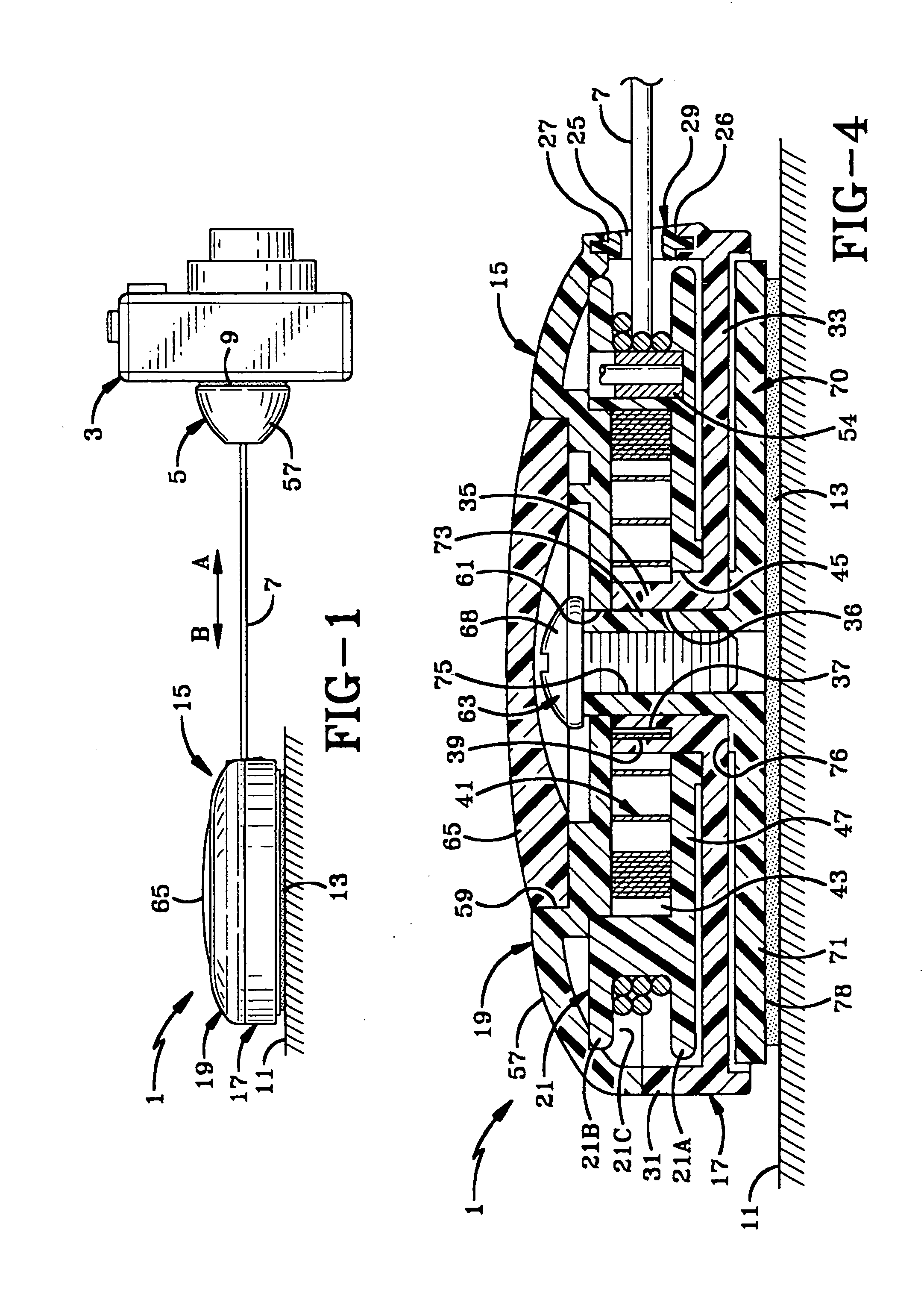
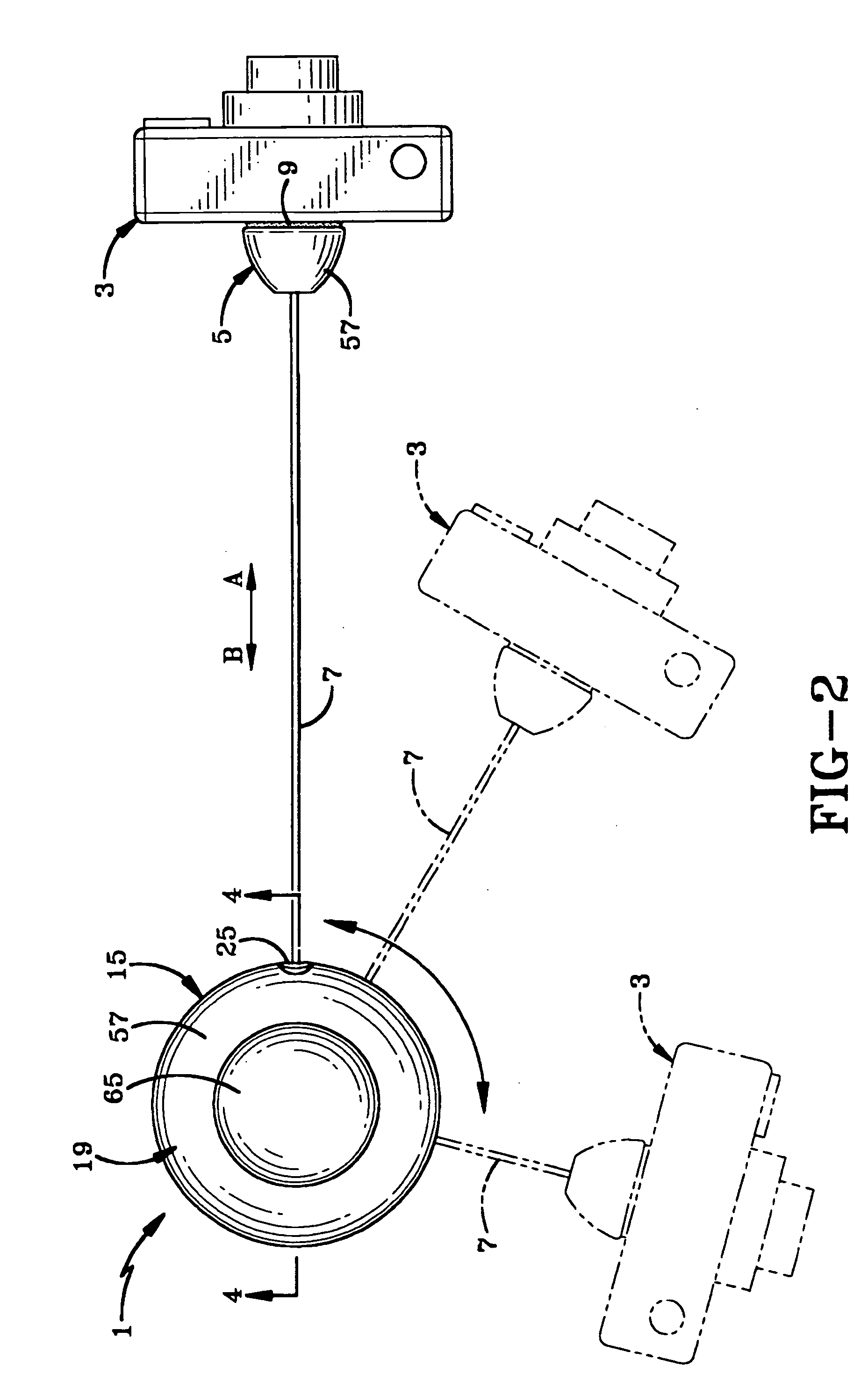
[0018]The recoiler of the present invention is indicated generally at 1, and is shown in FIGS. 1 and 2 being connected to an item of merchandise 3. Merchandise 3 is depicted as being a camera. However any item of merchandise and other types of objects can be connected to the recoiler by an attachment pad 5, which is connected to the distal end of a cable 7. Attachment pad 5 can be connected easily to merchandise 3 by a disc-shaped pressure sensitive adhesive pad 9 or other type of attachment device. Recoiler 1 preferably is mounted on a support structure 11 by a second pressure sensitive adhesive pad 13 or other type of mechanism.

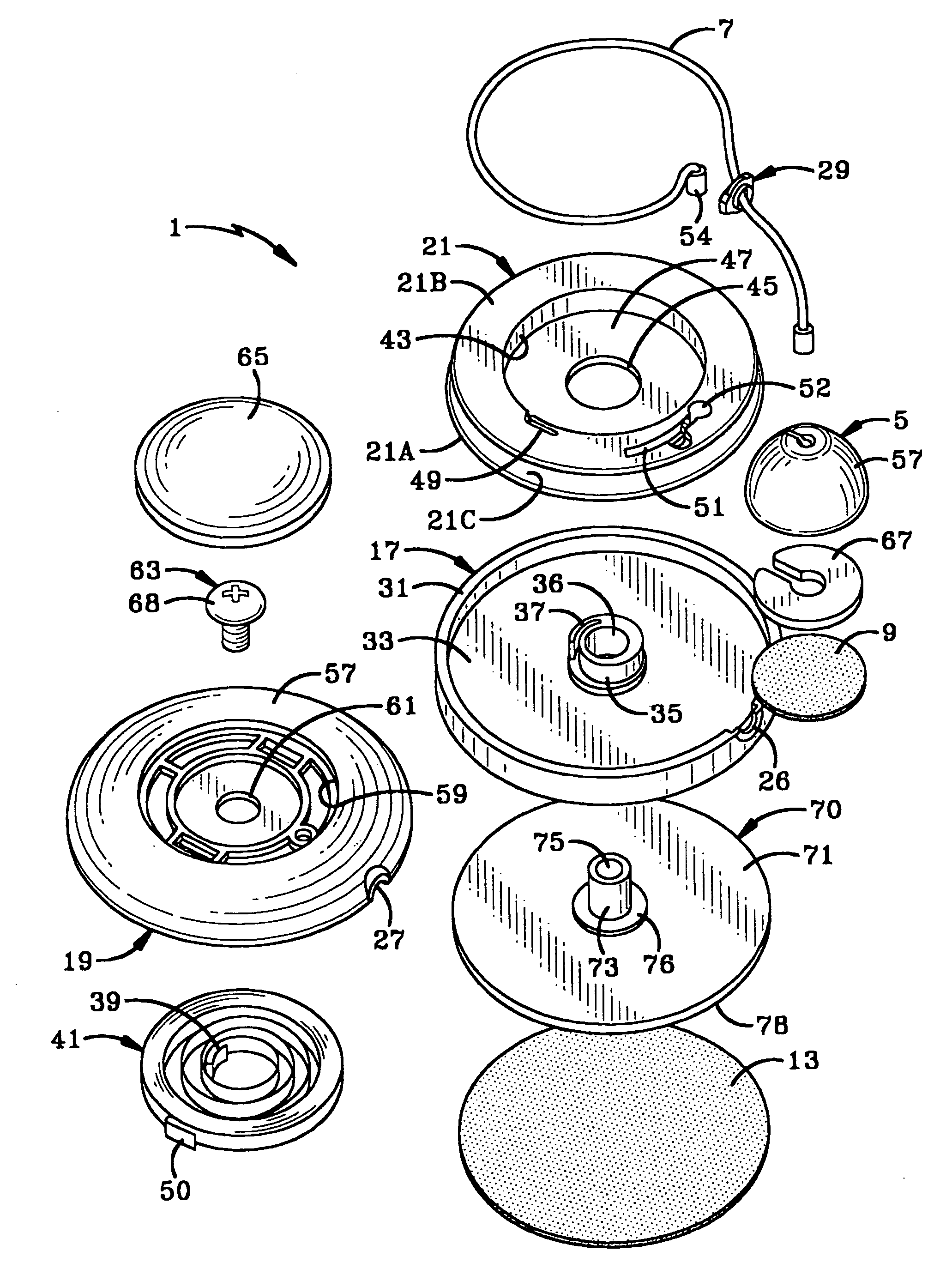
[0019]The components of recoiler 1 are best shown in FIGS. 3 and 4. Recoiler 1 includes a housing indicated generally at 15, which includes a bottom housing member 17 and a top housing member 19, each of which preferably is formed as a one piece member of plastic material enabling them to be mass produced at a relatively low cost. A spool 21 stores a predet...


PUM


Abstract

A recoiler has a retractable cable with an attachment pad on the distal end of the cable for attachment to an item of merchandise. The cable is stored on a spring biased spool located within a recoiler housing. The housing is freely rotatably mounted on a post extending upwardly from a base plate secured to the spool housing by a fastener and adapted to be secured to a support structure.

Description

BACKGROUND OF THE INVENTION[0001]1. Technical Field[0002]The invention relates to a recoiler having a retractable cable which is adapted to be connected to an item of merchandise to enable a customer to inspect the merchandise while retaining the merchandise in a secure position. More particularly, the invention relates to such a recoiler in which the recoiler mechanism is contained within a housing which is mounted on a swivel enabling it to rotate so that the cable extends at the correct angle at all times from the recoiler to the merchandise connected thereto.[0003]2. Background Information[0004]Numerous types of recoilers have been developed which include a cable that is extendable out of the recoiler and attached to an item of merchandise to enable a potential customer to inspect and handle the merchandise conveniently, yet prevent the merchandise from leaving a display counter. These recoilers have some type of spring mechanism which is contained in the recoiler to exert a bia...

Claims


Application Information

Patent Timeline
IPC IPC(8): B65H75/48
CPCA45F5/004B65H75/446A47F7/024
Inventor BELDEN, DENNIS D.SANKEY, JAMES K.
Owner INVUE SECURITY PROD INC
Learn More