Wire winding apparatus, method for wire winding and wire wound bobbin

a wire winding and bobbin technology, applied in the direction of rolling mill control devices, manufacturing tools, drawing dies, etc., can solve the problem of insufficient density of wire wound

Active Publication Date: 2008-02-14
AISIN SEIKI KK
View PDF19 Cites 6 Cited by
  • Summary
  • Abstract
  • Description
  • Claims
  • Application Information

AI Technical Summary

Problems solved by technology

With constructions of known devices and methods where a wire with a rounded cross section is wo

Method used


Image

  • Wire winding apparatus, method for wire winding and wire wound bobbin
  • Wire winding apparatus, method for wire winding and wire wound bobbin
  • Wire winding apparatus, method for wire winding and wire wound bobbin

Examples


Embodiment Construction

[0017]An embodiment of the present invention will be described below with reference to the attached drawings hereinafter.

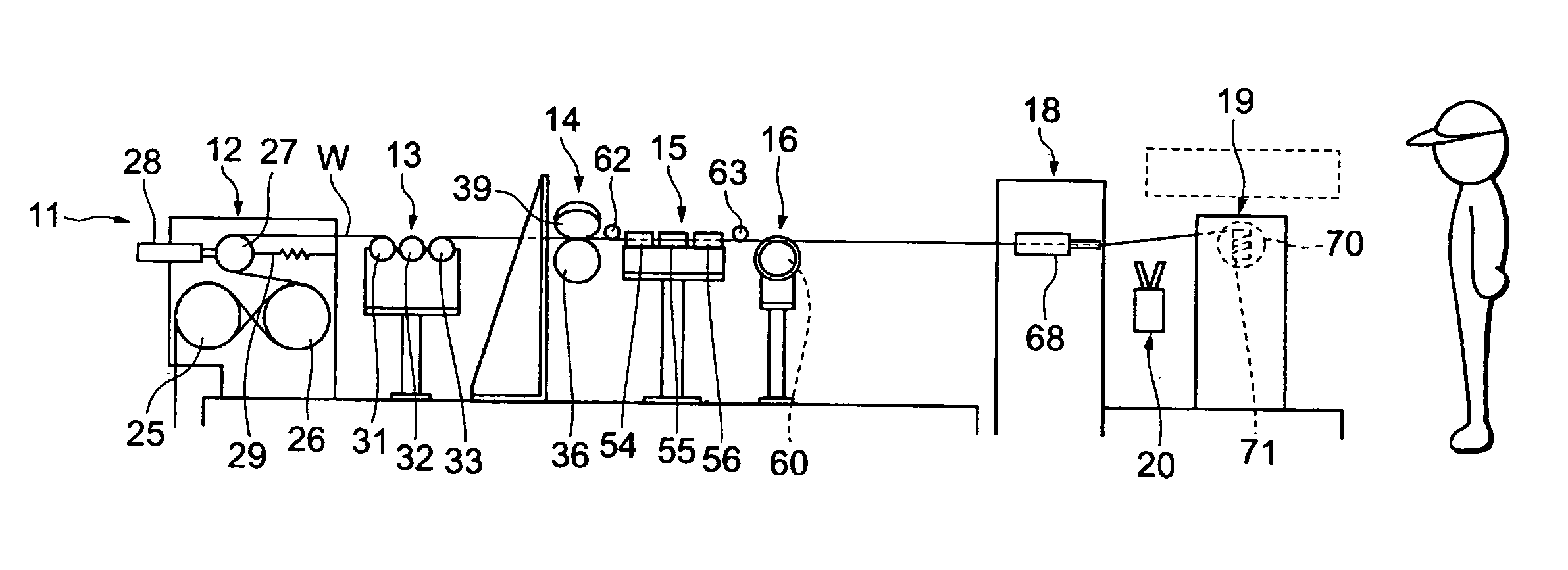
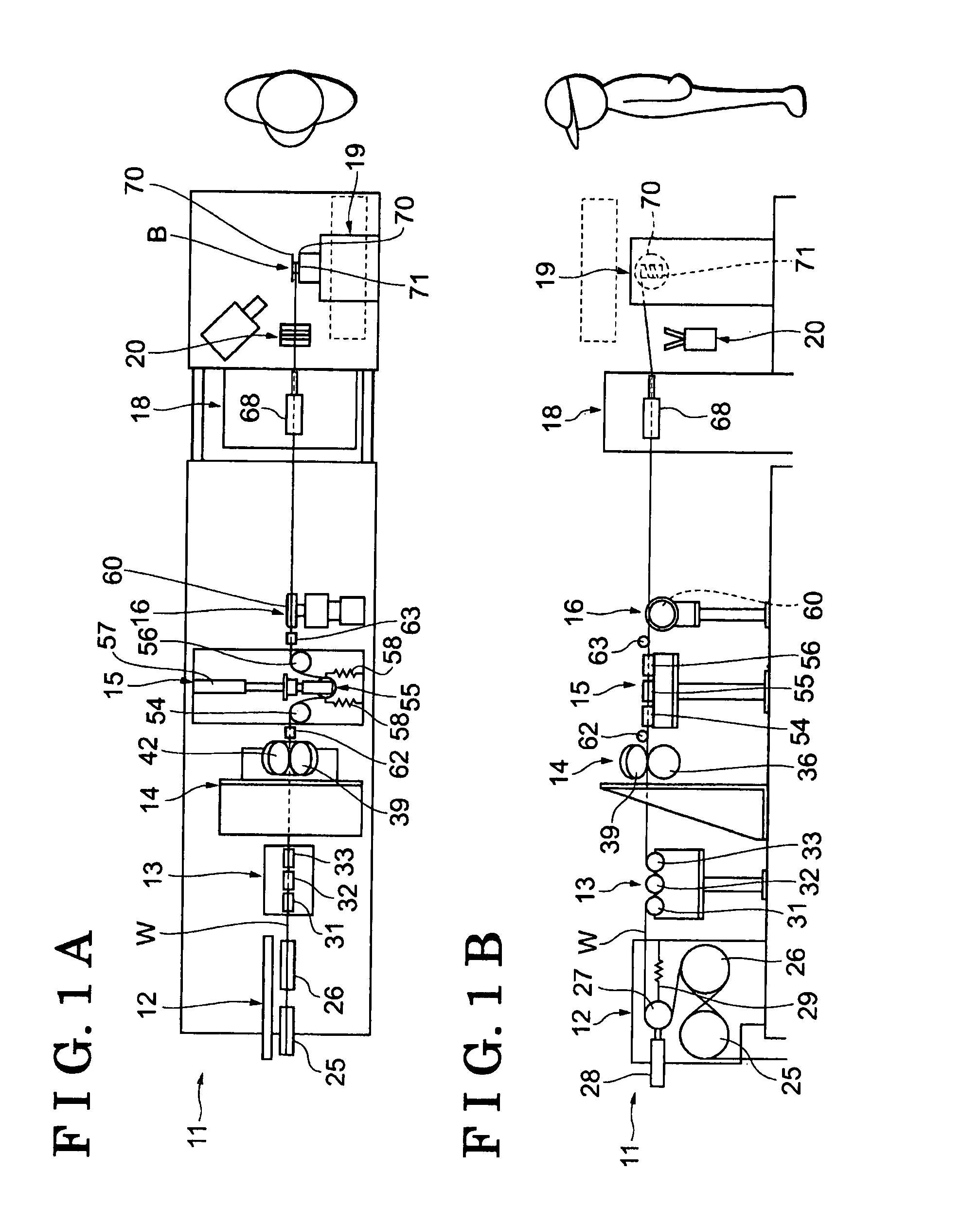
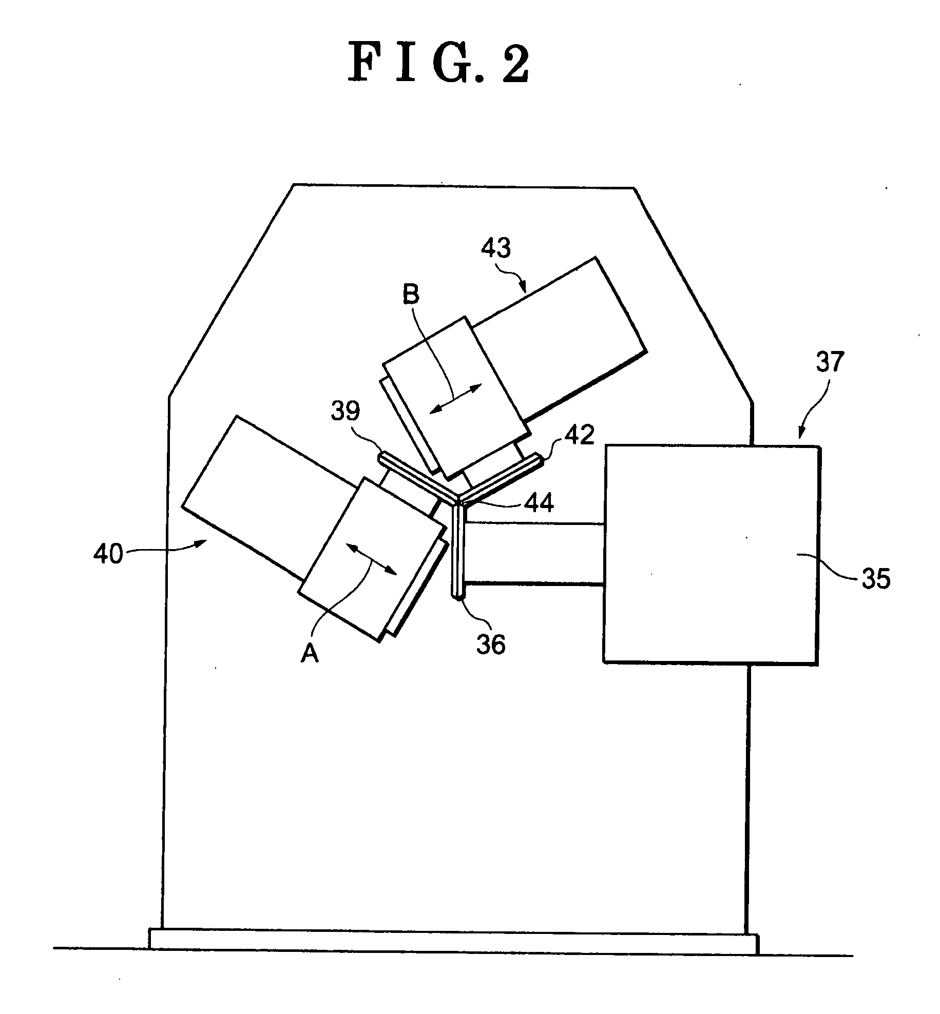
[0018]As shown in FIG. 1, a wire winding apparatus 11 includes, in order from the upstream for feeding a wire W, a servo tension device 12 serving as a wire feeding device feeding the wire W with a rounded cross section, a tension gauge 13 that detects a tension of the wire W, a rolling and forming device 14 serving as a forming device which forms the wire W having a rounded cross section into the wire W having a substantially polygonal cross section, for example, a substantially equilateral hexagonal cross section by means of a tension force while the wire W is passing therethrough, a simple tension device 15 serving as a tension adjusting device which adjusts the tension of the wire W, a wire speed measurement device 16 that detects a speed of the wire W, a nozzle unit 18 in which the wire W passes through and a spindle unit 19 serving as a winding device which ...


PUM

PropertyMeasurementUnit
Tensionaaaaaaaaaa

Abstract

A wire winding apparatus for winding a wire on a bobbin includes a forming device forming the wire having a rounded cross section to have a polygonal cross section and a winding device winding the wire formed by the forming device on the bobbin.

Description

CROSS REFERENCE TO RELATED APPLICATIONS[0001]This application is based on and claims priority under 35 U.S.C. § 119 to Japanese Patent Application 2006-220131, filed on Aug. 11, 2006, the entire content of which is incorporated herein by reference.FIELD OF THE INVENTION[0002]This invention generally relates to a wire winding apparatus, a method for wire winding and a wire wound bobbin.BACKGROUND[0003]Manufacturing processes for an electric motor include a process of winding wire on a bobbin, where various ingenuities have been implemented. When a wire with a rounded cross section is wound on a cylindrical surface of a round bobbin, for example, the diameter increases as the number of windings progresses, which increases the speed with a constant acceleration. According to JP7-106178A, a wire tension device is provided to respond to the speed change. According to 2005-235966A, when winding a wire having a rounded cross section on a square column surface of a rectangular bobbin, windi...

Claims


Application Information

Patent Timeline
IPC IPC(8): H01F41/06
CPCB21C3/08B21C47/04B65H54/2848B65H55/04H01F41/0691H01F27/2823H01F41/0633H01F41/0679B65H2701/3913H01F41/077H01F41/082H01F41/094
Inventor KANOH, NOBUTAKAKATO, HISASHIMORITA, TETSUYAHOSHINO, AKINORI
Owner AISIN SEIKI KK
Why Eureka
Try Eureka