
Center-routed kite safety device

Active Publication Date: 2008-02-14
SEE DANO +1
View PDF20 Cites 11 Cited by
  • Summary
  • Abstract
  • Description
  • Claims
  • Application Information

AI Technical Summary

Benefits of technology

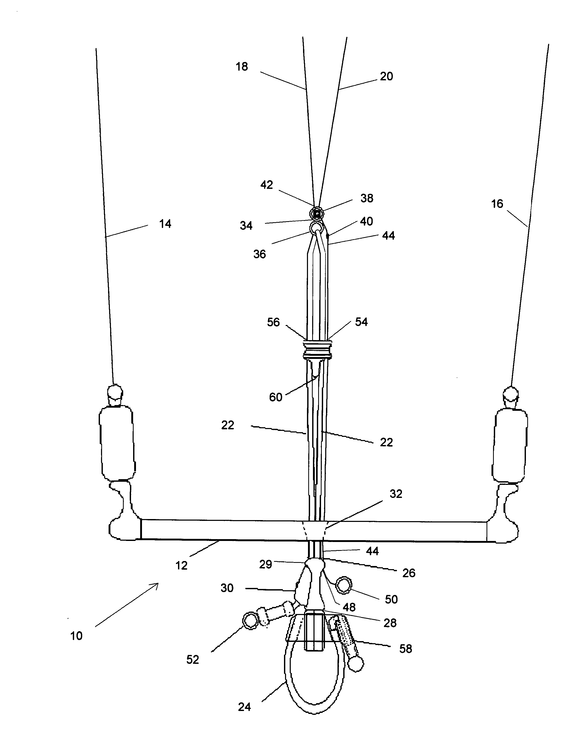
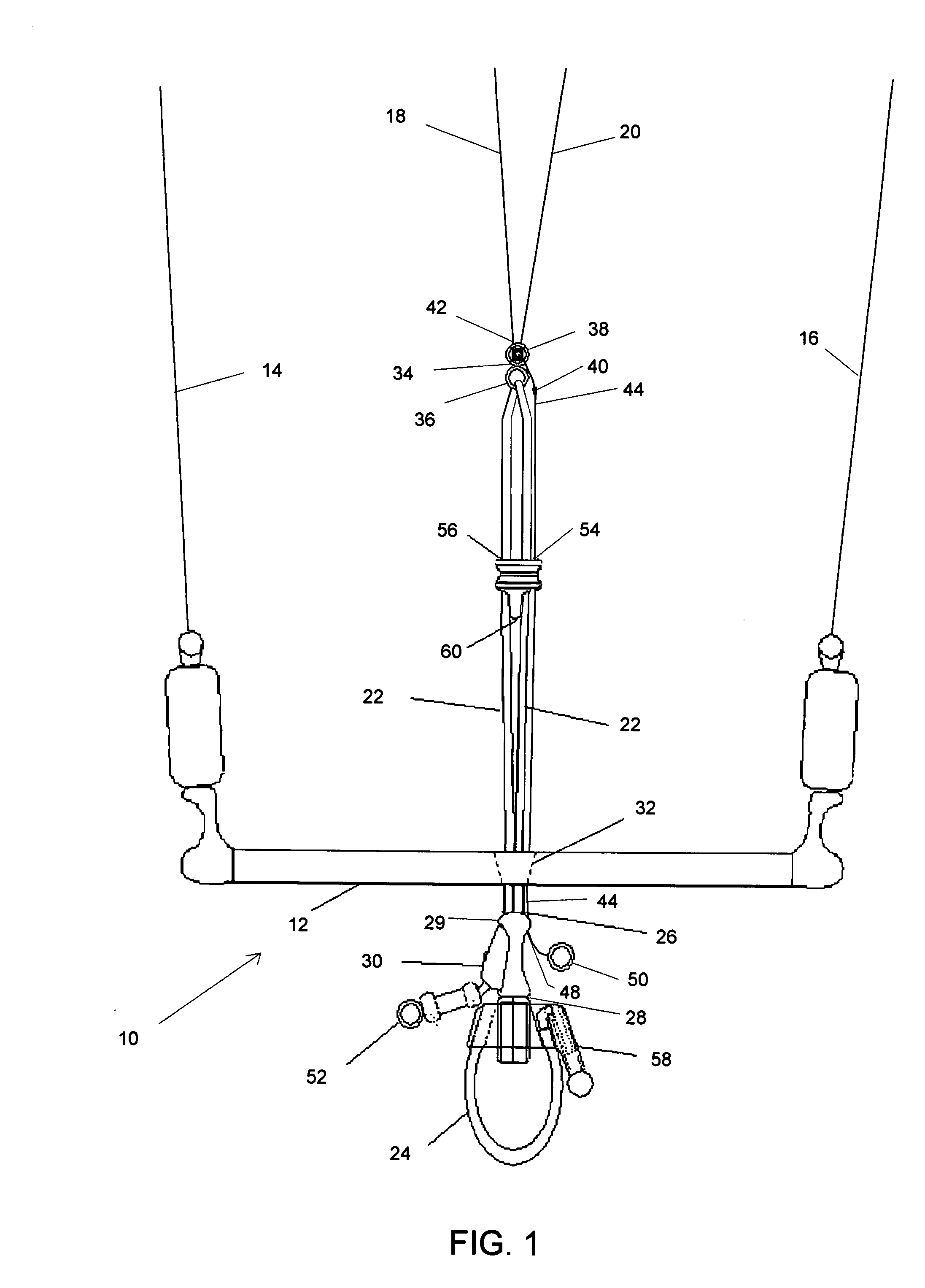
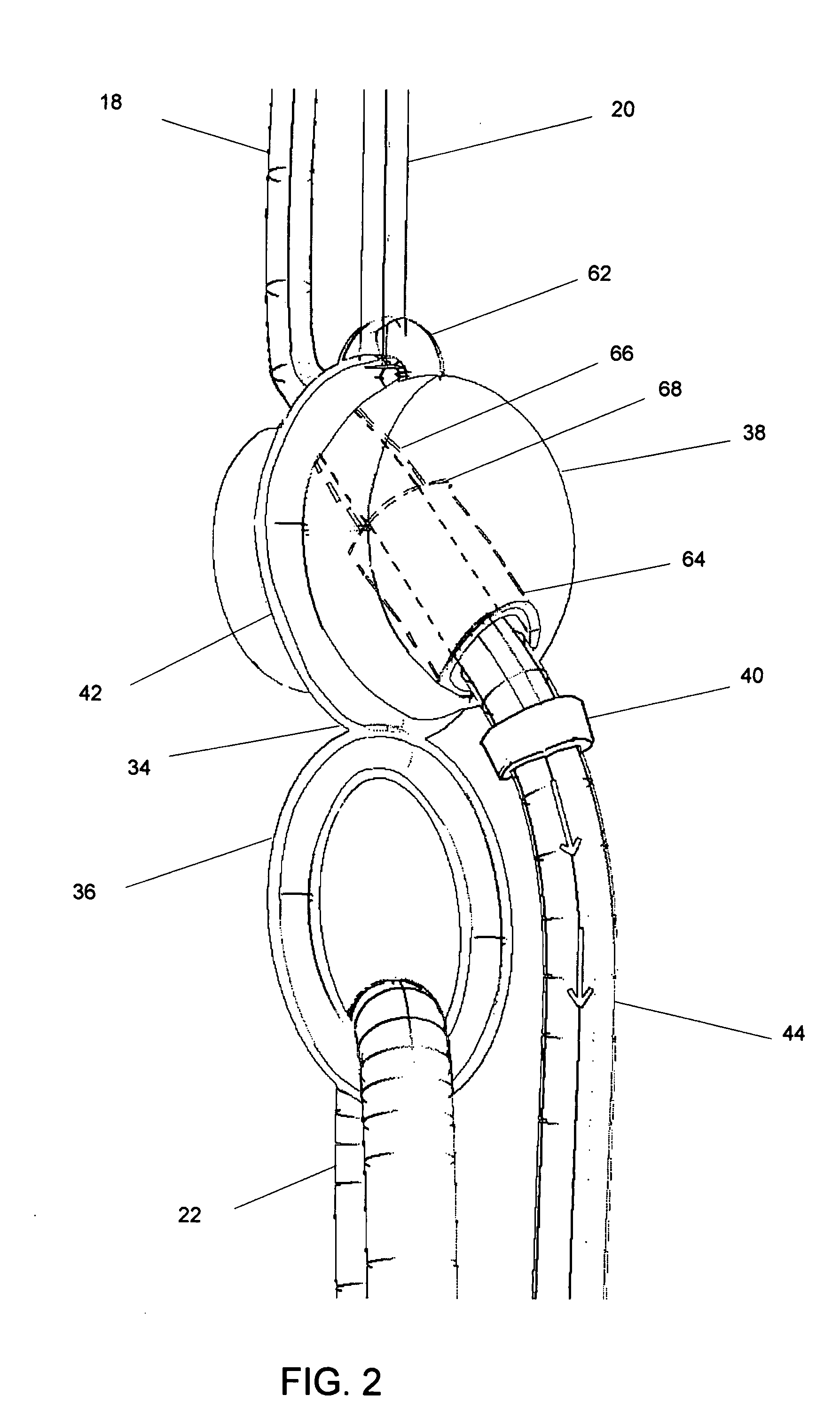
[0017] Preferably, the stopper housing has a large bore portion and a small bore portion, wherein the small bore portion prevents travel of the increased diameter element through the stopper housing. Also preferably, the large bore portion is configured to engage the increased diameter element of the first flying line with friction and releasably retain the increased diameter element. Also preferably, the increased diameter element has a diameter less than the diameter of the aperture on the bar.
[0021] The invention also includes a method for controlling an aerodynamic wing comprising the steps of providing a bar having opposing ends adapted to apply steering forces to the aerodynamic wing, at least two flying lines used to transmit forces to and from the aerodynamic wing, a stopper housing secured to the control device and a flying line extension extending from a first flying line of the at least two flying lines through an aperture on the bar, wherein the first flying line is routed through the stopper housing and wherein the first flying line has an increased diameter element configured to engage the stopper housing and prevent travel of the increased diameter element through the stopper housing, attaching a safety tether between a user and the flying line extension to restrain the first flying line, and depowering the aerodynamic wing by releasing the bar so that the first flying line runs through the stopper housing and the aperture to create slack in flying lines other than the first flying line.

Problems solved by technology

However, these same forces can also pose significant safety hazards to the user and to bystanders when inadequate control is provided.
This can occur if the wind strength increases beyond an acceptable amount, if the user does not or cannot utilize the control system appropriately or if the control system becomes compromised, such as by twisting, tangling or breaking the lines.
Ideally, this has the effect of corrupting the aerodynamic profile of the kite so that essentially all the lifting forces are extinguished.
However, the conventional safety depower systems suffer from a number of drawbacks, including the possibility that the kite will not adequately depower, the significant chance that the lines will become tangled and the difficulty in relaunching the kite after it has been depowered.
In particular, the choice of how to restrain one of the flying lines while allowing slack in the remaining lines presents significant design challenges.
As the control bar is pulled away from the user by the tension in the flying lines, significant slack develops in all the lines except for the one secured by the tether.
This arrangement prevents the kite from maintaining an effective aerodynamic profile and the kite is unable to generate significant power.
Despite the general effectiveness of these prior art safety designs, the attachment of the safety tether to the flying line is awkward and raises the risk of tangling either with the user or with the other kite control mechanisms.
If the tether becomes so tangled that the line cannot pull smoothly back from the stop, then the ability of the system to depower the kite is compromised and may not effectively protect the user during deployment.
Another difficulty posed by the conventional depower systems is the twisting of flying lines that can occur during normal kite operation.
Unfortunately, the presence of the safety tether can interfere with this process, leaving the tether twisted about the control lines.
Correspondingly, this interferes with the user's ability to control the kite and undermines the safety system as described above.

Method used


Image

  • Center-routed kite safety device
  • Center-routed kite safety device
  • Center-routed kite safety device

Examples


Embodiment Construction

[0028] Before describing the present invention in detail, it is to be understood that this invention is not limited to particularly exemplified materials, methods or structures as such may, of course, vary. Thus, although a number of materials and methods similar or equivalent to those described herein can be used in the practice of the present invention, the preferred materials and methods are described herein.

[0029] It is also to be understood that the terminology used herein is for the purpose of describing particular embodiments of the invention only and is not intended to be limiting.

[0030] Unless defined otherwise, all technical and scientific terms used herein have the same meaning as commonly understood by one having ordinary skill in the art to which the invention pertains.

[0031] Further, all publications, patents and patent applications cited herein, whether supra or infra, are hereby incorporated by reference in their entirety.

[0032] Finally, as used in this specifica...


PUM


Abstract

A control device for use with an aerodynamic wing including a bar having a safety system that restrains one of the flying lines by routing an attachment through an aperture on the bar. Preferably, the system includes a stopper housing that engages an increased diameter element of the flying line. During normal operation, the increased diameter element is secured by the stopper housing, preventing the flying line from being pulled beyond the stopper housing. When the safety system is deployed, the increased diameter element is pulled from the stopper housing and slack is developed along the remaining flying lines to depower the kite.

Description

CROSS-REFERENCE TO RELATED APPLICATIONS [0001] This application is a continuation-in-part of U.S. patent application Ser. No. 11 / 100,911, filed Apr. 6, 2005 and a continuation-in-part of U.S. patent application Ser. No. 11 / 267,947, filed Nov. 3, 2005.FIELD OF THE PRESENT INVENTION [0002] The present invention relates generally to devices for controlling inflatable power or traction kites. More particularly, the invention relates to a bar for controlling a kite having a safety system with improved features. BACKGROUND OF THE INVENTION [0003] Considerable effort is being expended to develop wings capable of generating tractive force for the purposes of powering a user on a variety of vehicles that are tethered solely by flexible lines. Such wings can generally be considered kites. The development of kites capable of generating significant force has made possible numerous recreational pursuits. For example, kite surfing or kite boarding refers to a sport involving the use of a wind pow...

Claims


Application Information

Patent Timeline
IPC IPC(8): B64C31/06
CPCB63B35/7979B63B35/7933B63H8/16B63H8/18B63H8/52B63H8/58
Inventor SEE, DANOBERNARD, AMERY
Owner SEE DANO
Learn More