Ribbed post

a post and rib technology, applied in the field of ribbed posts, can solve the problems of affecting so as to prevent unintended dislodging of the wire and maintain the stability of the pos

Inactive Publication Date: 2008-02-14
JONES BRADLEY JEFFERSON
View PDF49 Cites 2 Cited by
  • Summary
  • Abstract
  • Description
  • Claims
  • Application Information

AI Technical Summary

Benefits of technology

[0009]On the exterior of the post are two substantially co-planar ribs, ridges, clips or protrusions, collectively and alternatively referred to herein as “ridges” or “flanges”. Each ridge or flange contains an array or series of spaced-apart C-shaped mounted or formed notches or apertures to hold flexible filaments such as wires and, without intending to be limiting, trellis wires. As used herein, reference to “wires” is intended to include wires, lines, strings or other elongate flexible filaments. Each aperture, that is to say, each wire holder, has an opening oppositely disposed relative to the post. Each opening is formed between a pair of resilient opposed facing flanges. Advantageously, and without intending to be limiting, each pair of flanges is spaced apart by a distance which is slightly less than the diameter of the wire to be inserted through such opening into the wire holder cavity. When a wire is placed against the aperture opening and pressure applied against the wire in the direction of the post, the flanges are sufficiently resilient so as to slightly deform enough to allow the wire to enter through the opening. Once the wire has entered the aperture and the external pressure against the opening has ceased, the flanges return to their un-deformed state thereby inhibiting unintended dislodgement of the wire from the receiving wire cavity. In use, weight-bearing wires are mounted into the wire holders so as to alternate sequentially from a ridge on one side of the post to the opposite ridge and so on along the length of the post so that only every second wire-receiving cavity on each ridge is used and the wires are alternatingly staggered upwardly along the length of the post. The opposing forces acting on the post are thereby equalized to assist in maintaining the stability of the post while in use.

Problems solved by technology

Consequently, the plants themselves, and potentially any fruits borne by them may contain traces of arsenic.
As the wood ages and dries, the staples or clips often loosen and pop out.
This may result in damage to the plant which depended from the wire supported by the loosened staples or clips.
Where the loosened staples or clips fall onto the ground, damage to vehicle tires may also result.
Where long lengths of wires are required as in, for example, many field applications, this method requires longer construction time and is often impractical.
It may also result in increased wear on the post at the points where the wire contacts the posts, particularly when the wire is bearing the weight of plants.
Depending upon the manner in which they are constructed and installed, metal posts may have strength and durability problems in the field.
Metal posts may also tend to absorb significant amounts of heat during the day, which heat may be released at night to the detriment of the plants and fruit proximate to such metal posts.

Method used


Image

  • Ribbed post
  • Ribbed post
  • Ribbed post

Examples


Embodiment Construction

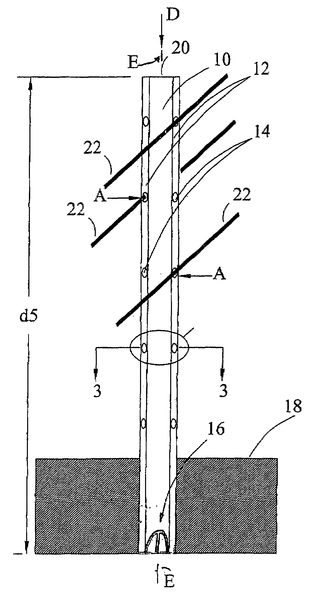
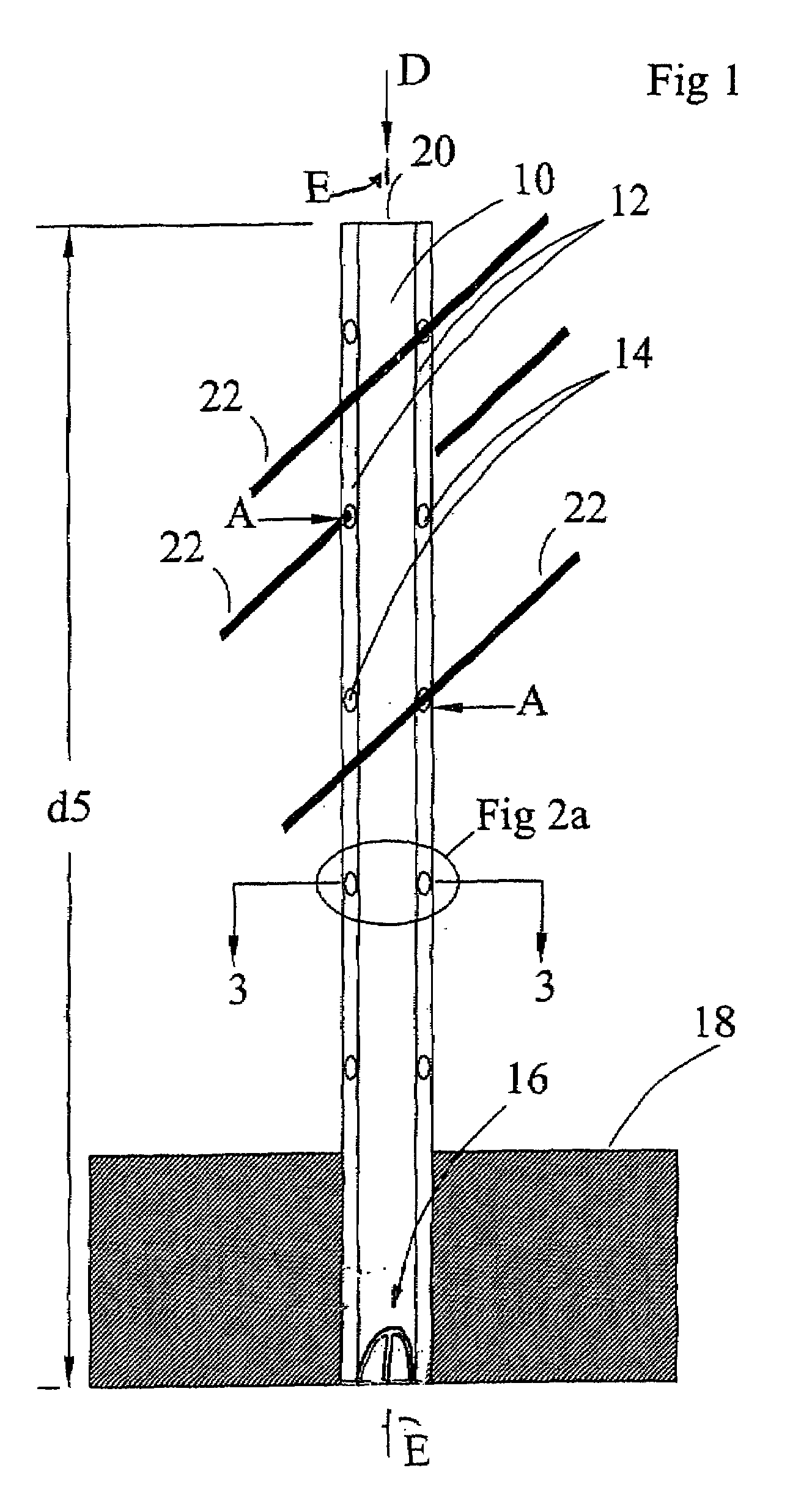
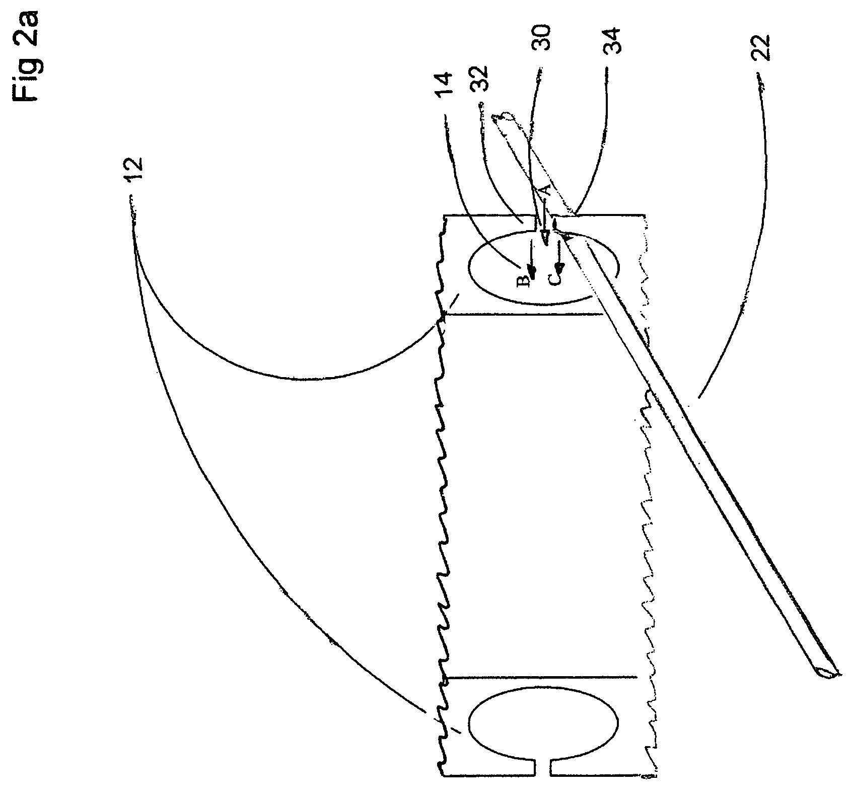
[0016]In the accompanying Figures, wherein like reference numerals denote corresponding parts in each view, FIG. 1 illustrates basal end 16 of post 10 driven into ground 18. It is understood that post 10 would be mounted sufficiently deeply into ground 18 so as to be free-standing when un-loaded. Post 10 is in one embodiment a hollow, cylindrical post. The post may be flat and sealed on apical end 20, and is preferably chisel shaped on basal end 16. The chiseled shape of basal end 16 of post 10 is such that post 10 may be inserted into an augered hole or into ground 18 with a post-pounder or other suitable post driving means thereby securing post 10 in ground 18 without twisting the direction of the flanges, keeping them parallel to adjoining post flanges in the trellis line. A pair of oppositely disposed ridges 12 are substantially co-planar, each ridge 12 containing a series such as linear spaced-apart arrays of notches or apertures 14 (collectively herein “apertures”). Apertures ...


PUM


Abstract

A post for mounting to the ground and for supporting elongate flexible filaments transverse to the post. The hollow member has opposite first and second ends. The first end is adapted for mounting to the ground. Stiffeners are mounted within the hollow post so as to extend between the first and second ends. First and second oppositely disposed elongate raised flanges are mounted on the post so as to extend outwardly therefrom. The flanges extend between the first and second ends. The raised flanges each have a longitudinally spaced apart array of filament receiving cavities. Each cavity is an aperture through a corresponding raised flange and has an opening providing access into the aperture from a distal edge of the corresponding raised flange for receiving therethrough the filament for mounting the filament into the aperture. Each opening has a constriction having an opening dimension which is substantially equivalent to a diameter of the filament.

Description

FIELD OF THE INVENTION[0001]This invention relates to the field of post and wire systems for supporting growing plants and trees including fruit bearing varieties, such as grapes used for making wine.BACKGROUND OF THE INVENTION[0002]Certain plant crops such as, without intending to be limiting, grape vines, require support in order to train the plant to grow in a desired fashion and to reduce fruit spoilage by keeping developing and ripened fruit off of the ground. Plant support systems are characteristically comprised of a trellis system having one or more wires strung between posts. In a vineyard trellis system, for example, one to two wires are strung between posts spaced approximately 16 to 24 feet apart, which posts are ordinarily approximately 3 to 4 inches in diameter.[0003]The posts are commonly made of wood which has been pressure-treated with a preservative so as to slow the rate at which they rot. One such wood preservative is chromated copper arsenate which contains arse...

Claims


Application Information

Patent Timeline
Patent Type & Authority Applications(United States)
IPC IPC(8): E04H17/02
CPCE04H17/12
Inventor JONES, BRADLEY JEFFERSON
Owner JONES BRADLEY JEFFERSON
Why Eureka
Try Eureka