Adjustment arrangement in a suspension hanger assembly

Active Publication Date: 2008-02-14
VOLVO LASTVAGNAR AB
View PDF14 Cites 15 Cited by
  • Summary
  • Abstract
  • Description
  • Claims
  • Application Information

AI Technical Summary

Benefits of technology

[0013]Through the use of the bushing pin adjustment arrangement system described hereinabove, stress is minimized in the suspension hanger assembly which prolongs the useful life of the mechanism, prevents the pin's binding in the hanger which can cause difficulties in

Problems solved by technology

There are, however, deficiencies associated with these designs.
A common problem experienced in existing bushing adjustment mechanisms, such as those disclosed in the patents referenced above, is that a bushing pin can easily get crosswise and bind i

Method used


Image

  • Adjustment arrangement in a suspension hanger assembly
  • Adjustment arrangement in a suspension hanger assembly
  • Adjustment arrangement in a suspension hanger assembly

Examples


Embodiment Construction

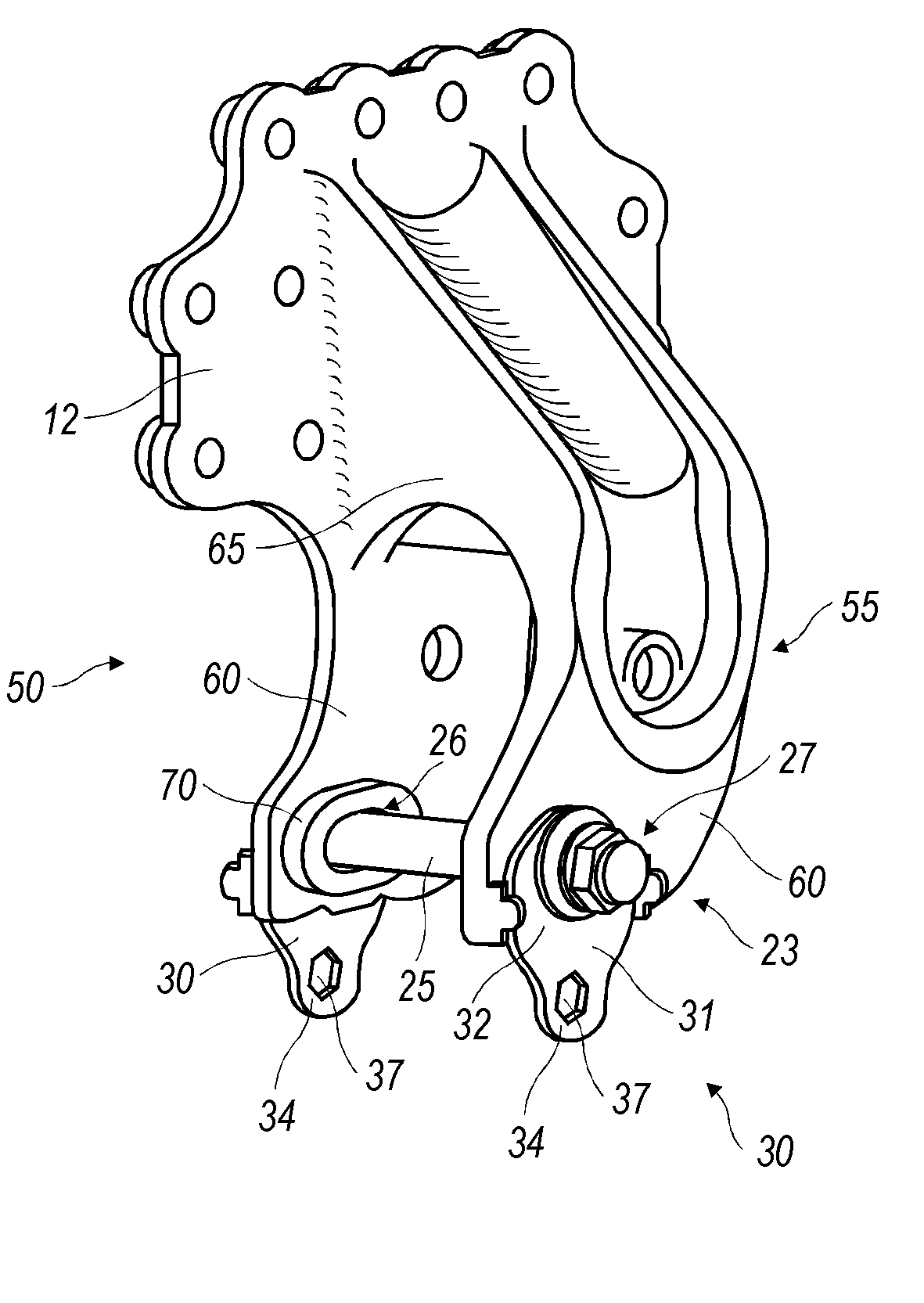
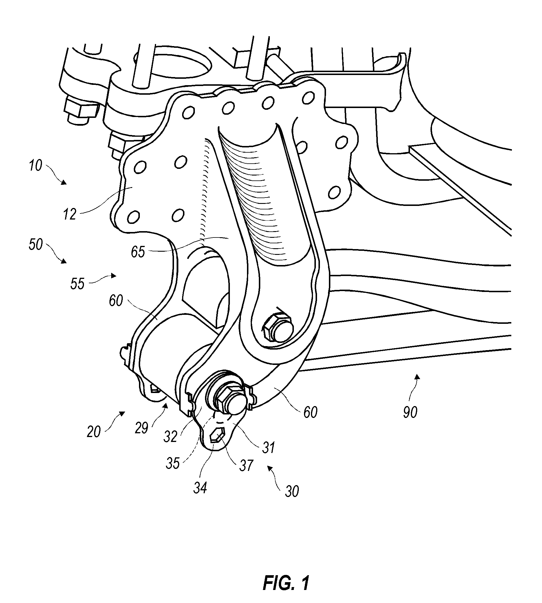
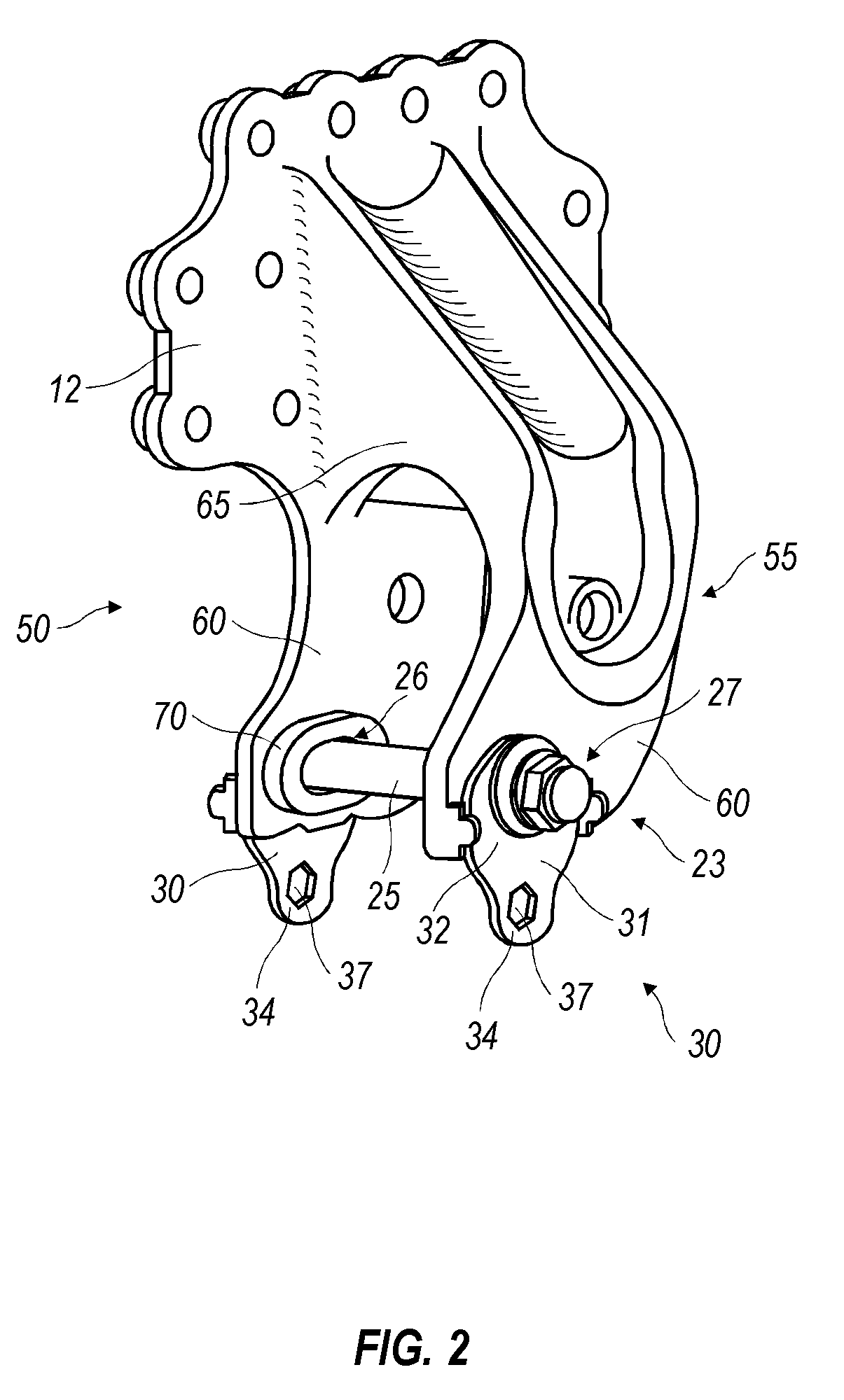
[0019]Referring to FIG. 1, a support assembly 10 configured according to the present invention is shown for suspending a load bearing bushing 29 on a hanger bracket 55 of a hanger assembly 50 which constitutes part of a vehicular suspension. The hanger assembly 50 can be connected to the vehicle by a support portion or connective plate 12, typically at the frame of the vehicle. The hanger bracket 55 of the hanger assembly 50 is generally U-shaped with two hanger legs 60 projecting substantially away from the vehicle in a spaced-apart, essentially parallel orientation to one another. As shown, the legs 60 are joined together by the interconnection 65. Each leg 60 is shown as being of substantially plate-like construction, and extends in an essentially downward direction below the vehicle frame. This orientation and construction is preferred, but not required.

[0020]An elongate aperture or slot 70 is cut or otherwise formed in each of the two legs 60. A bushing assembly 20 includes a b...


PUM


Abstract

An adjustment arrangement in a suspension hanger assembly that can be used to square the orientation of an axle with the travel direction of the incorporating vehicle. The adjustment arrangement includes a hanger bracket that has a pair of substantially parallel, spaced apart hanger legs projecting generally away from the vehicle and each of the hanger legs has an elongate aperture or slot that is mutually aligned, one with the other. A bushing pin is inserted through both elongate apertures with opposite end portions of the pin being similarly positioned in each of the apertures. A substantially squared orientation is established between the hanger bracket and the bushing pin. A pair of adjustment devices are provided, one each, in association with a respective end portion of the bushing pin. The devices are configured to synchronously move both end portions of the bushing pin to similar positions in the elongate apertures thereby maintaining the substantially squared orientation between the hanger bracket and the bushing pin. Each of the adjustment devices are arranged to be rotated about a floating axis relative to the hanger bracket and to have a tool-receiving aperture eccentrically located relative to that floating axis. The tool-receiving apertures are configured to simultaneously receive a common actuating tool for affecting synchronous rotation of the adjustment devices.

Description

TECHNICAL FIELD[0001]The present invention relates to suspension assemblies for vehicles; and more particularly, to adjustment mechanisms for suspension hanger assemblies used for squaring the orientation of an axle of the vehicle to the travel direction.BACKGROUND ART[0002]In most wheel-based land vehicles and in particular heavy-duty trucks, the non-steering wheels are typically paired on axles that are connected to the vehicle by an appropriate suspension. These wheels may or may not be drive wheels interconnected with a transmission of the vehicle. In general, the vehicle's direction of travel is aligned with its long axis and the longitudinal axes of the axles are arranged to be squared or perpendicular thereto so that the rotating wheels turn in alignment with the travel direction. In this manner, excessive and abnormal tire wear is avoided, as is undue stress on the connections and components between the wheels and the vehicle. Still further, such aligned tracking of the whee...

Claims


Application Information

Patent Timeline
IPC IPC(8): B60G9/02
CPCB60G7/006B60G9/003B60G2200/31B60G2204/4302B60G2204/143B60G2204/42B60G2200/462
Inventor SVARTZ, BJORNBLONDE, PETERSURDHAR, STEVEPATRICIO, PAUL
Owner VOLVO LASTVAGNAR AB
Why Eureka
Try Eureka