
CCD Sensor And Method For Expanding Dynamic Range Of CCD Sensor

Inactive Publication Date: 2008-02-14
PLANMECA
View PDF9 Cites 11 Cited by
  • Summary
  • Abstract
  • Description
  • Claims
  • Application Information

AI Technical Summary

Benefits of technology

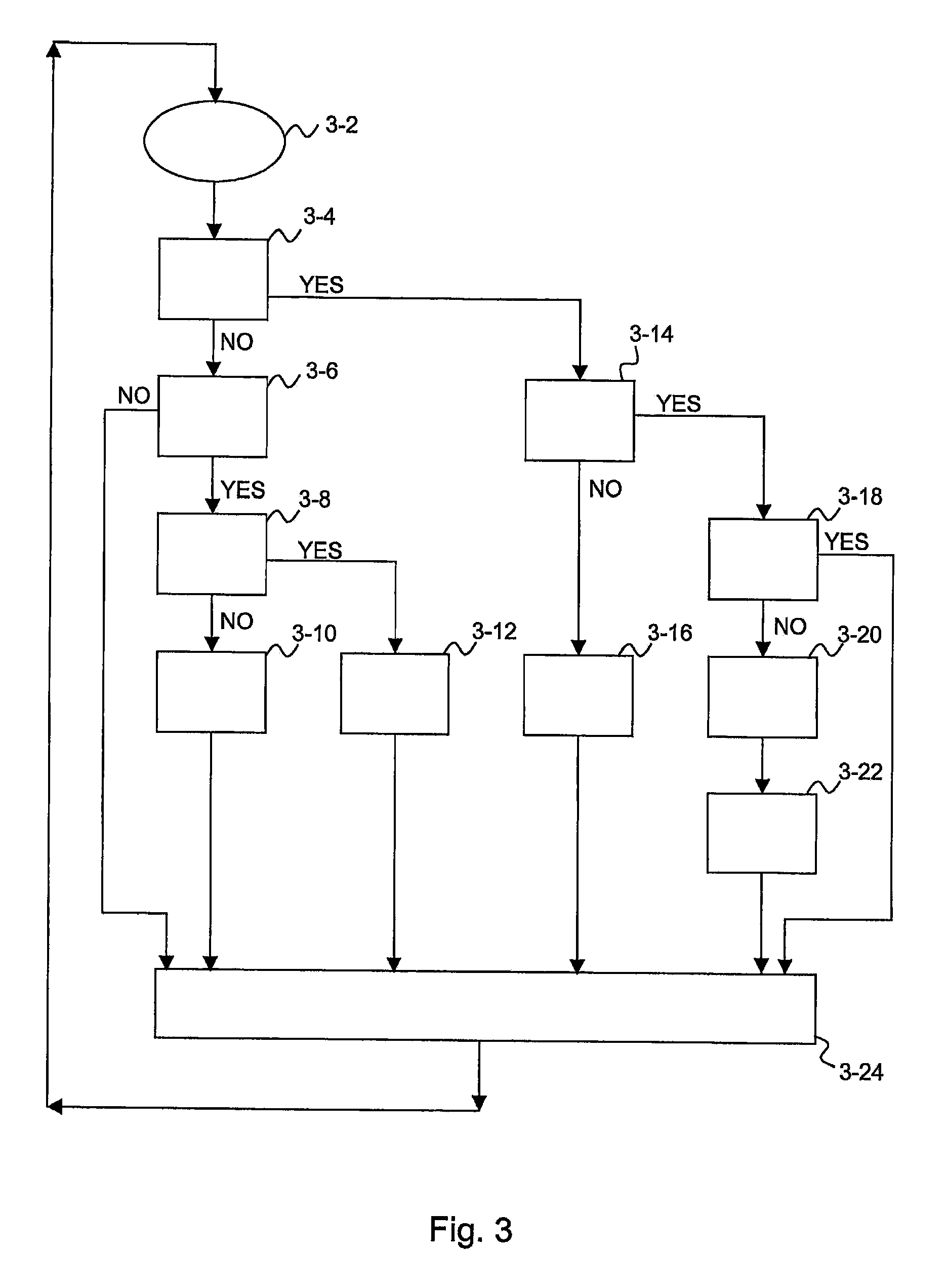
[0013] The method and system of the invention have the advantage of making it possible to expand the dynamic range of the CCD sensor and thus to prevent the sensor or a part of it from getting saturated.

Problems solved by technology

However, in certain situations, handling the charge of these combined pixels may be problematic.
Especially at higher signal levels, the signal coming from the image area may be so large that, with the selected binning, the charges can not be combined within the CCD sensor without a risk of saturation of the output amplifier.
However, these numeric values are not mutually comparable when film-based and digital systems are compared to each other.
Even if a film system would utilize only a small proportion of the total dynamics, in practice there would still be a very large number of greyness levels available.
Moreover, CCD based sensors do not forgive in situations of overexposure as do film-based systems, in which the reciprocal law (gradual saturation, s-curve of the film) causes a soft saturation and along with this a “compression”, i.e. an expansion of dynamics.
In other words, the charge received and contained in a pixel may be so large that it can not be handled in a binning situation in the read-out register and / or in the charge well of the output amplifier without a risk of saturation.
Especially in the case of larger binning operations, for example 3×3 and 4×4 (horizontal direction×vertical direction, the number of times of reading from the image area to the output register and from the output register to the read-out well), this becomes a problem.
In these situations, among others, there is an obvious risk of saturation if the system is otherwise tuned for optimal reception of the signal coming through the object.
This makes imaging of e.g. soft tissue areas impossible, and in the areas of saturation all the image information is lost.

Method used


Image

  • CCD Sensor And Method For Expanding Dynamic Range Of CCD Sensor
  • CCD Sensor And Method For Expanding Dynamic Range Of CCD Sensor
  • CCD Sensor And Method For Expanding Dynamic Range Of CCD Sensor

Examples


Embodiment Construction

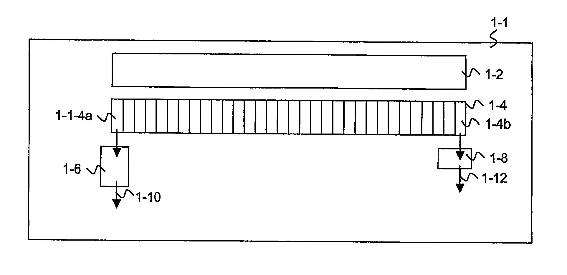
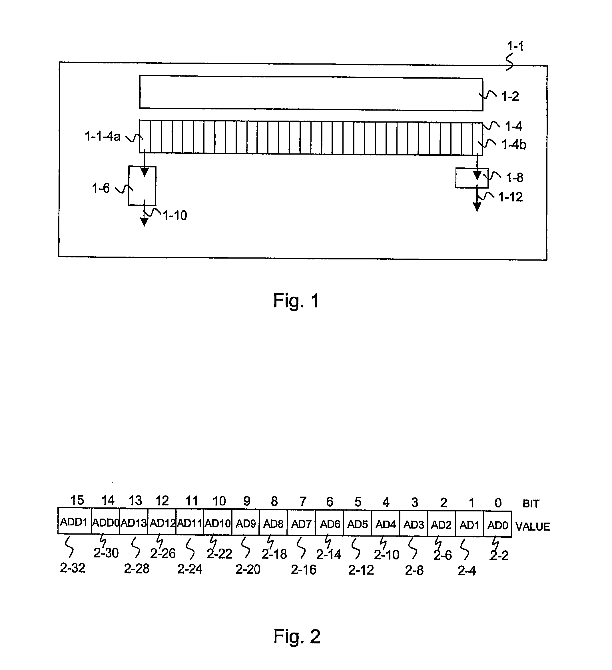
[0021] In the following, the invention and its preferred embodiments will be described by way of example with reference to a typical CCD sensor (manufactured e.g. by Atmel, Thomson) and charge capacity specifications optimized by also considering an automatic gain control function (AGC, Automatic Gain Control). The sensor may have e.g. the following properties:

[0022] Saturation charge of a separate single pixel (size: 33 μm×33 μm): 600.000 electrons.

[0023] Saturation charge of read-out register: [0024] a. 1.800.000 electrons.

[0025] Saturation charge of output amplifier A: [0026] a. 2.400.000 electrons.

[0027] Saturation charge of output amplifier B: [0028] a. 4.800.000 electrons.

[0029] When the sensor is operated in the horizontal direction (TDI direction, Time Delay Integration), with 3×3 binning the read-out register can hold a 100% signal of 3 successive pixels (3×600K=1800K, K=Kilo=1000). With 4×4 binning, four horizontal pixels charged to 75% of their capacity (1800K / 4 / 600*...


PUM


Abstract

A CCD sensor arrangement comprises a CCD sensor, which comprises a detector having an active area comprising pixels that receive charges; a read-out register functionally connected with the aforesaid active area; means for transferring charges from the active area to the read-out register; at least two read-out wells functionally connected with the read-out register, said at least two read-out wells having different capacities; means for transferring charges from the read-out register to the at least two read-out wells; means arranged in the sensor or in functional connection with the sensor for measuring the signal generated by the charges read out or being read out from said wells; and selection means for deciding during read-out of charges from said active area of the sensor, at least partly on the basis of the aforesaid measured signal, whether the read-out well to be used is to be changed. At least two read-out wells have different capacities, and means arranged in the sensor or in functional connection with the sensor for measuring the signal generated by the charges, and selection means for deciding at least partly on the basis of the aforesaid measured signal whether the read-out well to be used is to be changed.

Description

CROSS-REFERENCE TO RELATED APPLICATIONS [0001] This application is continuation-in-part of PCT applications PCT / FI2006 / 050151 and PCT / FI2006 / 050152, both of which are incorporated herein by reference.FIELD OF THE INVENTION [0002] The present invention relates to a CCD sensor and to a read out arrangement according to the preambles of claims 1 and 13. In addition, the invention relates to methods for expanding the dynamics of a CCD sensor according to the preambles of claims 16, 23 and 24. BACKGROUND OF THE INVENTION [0003] A CCD device (Charge Coupled Device) can be defined as being a semiconductor device wherein, due to the movement of electric charges, storage and collection of charges is possible. These charge transfer devices are used in dynamic, variable storage elements, which characteristically have a high information density. In CCD sensors intended for X-ray imaging, the charges used for image generation, which are formed on physical pixels, can be combined, binned. Binning...

Claims


Application Information

Patent Timeline
IPC IPC(8): H04N5/335H04N5/347H04N5/355H04N5/361H04N5/372
CPCH04N3/155H04N5/37206H04N3/1575H04N3/1562H04N25/46H04N25/583H04N25/711H04N25/713H04N25/71
Inventor DE GODZINSKY, CHRISTIAN
Owner PLANMECA
Learn More