Amplifier

Inactive Publication Date: 2005-06-21
ROHM CO LTD
View PDF4 Cites 5 Cited by
  • Summary
  • Abstract
  • Description
  • Claims
  • Application Information

AI Technical Summary

Benefits of technology

[0016]It is therefore an object of the invention to provide an improved amplifier having difference transistor pairs which provide an expanded dynamic range with a suppressed noise level.
[0027]In this arrangement, only the first amplifier circuit of the first difference pair which has negligibly small 1 / f noise is activated when the level of the input signal is lower than the predetermined level, thereby generating suppressed noise. When the input signal has a higher level than the predetermined level, the second amplifier of the second difference pair is activated to provide an expanded dynamic range.

Problems solved by technology

However, either type of difference pairs of transistors, incorporating p-type or n-type, has only a limited dynamic range for a given input signal, either in the upper or lower range of the signal.
However, in such conventional amplifier as mentioned above, noise characteristics are significantly worse than an amplifier including a p-type difference transistor pair Pd.
In order to suppress 1 / f noise, the sizes (channel lengths and / or channel widths) of the transistors may be enlarged, which however inevitably results in an increase in the area occupied by the amplifiers on the IC chip and hence the cost of the IC chip.

Method used


Image

  • Amplifier
  • Amplifier
  • Amplifier

Examples


Embodiment Construction

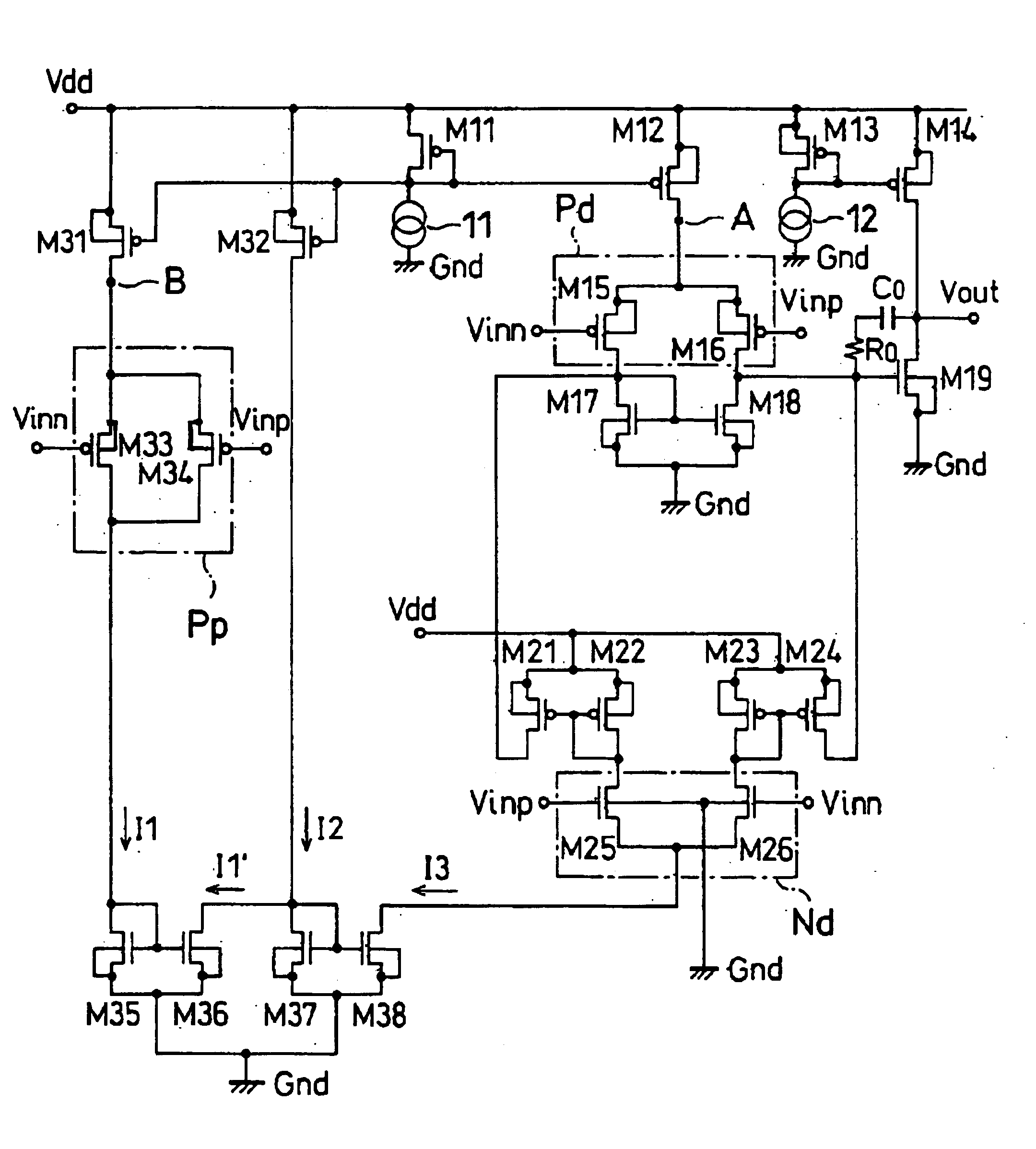
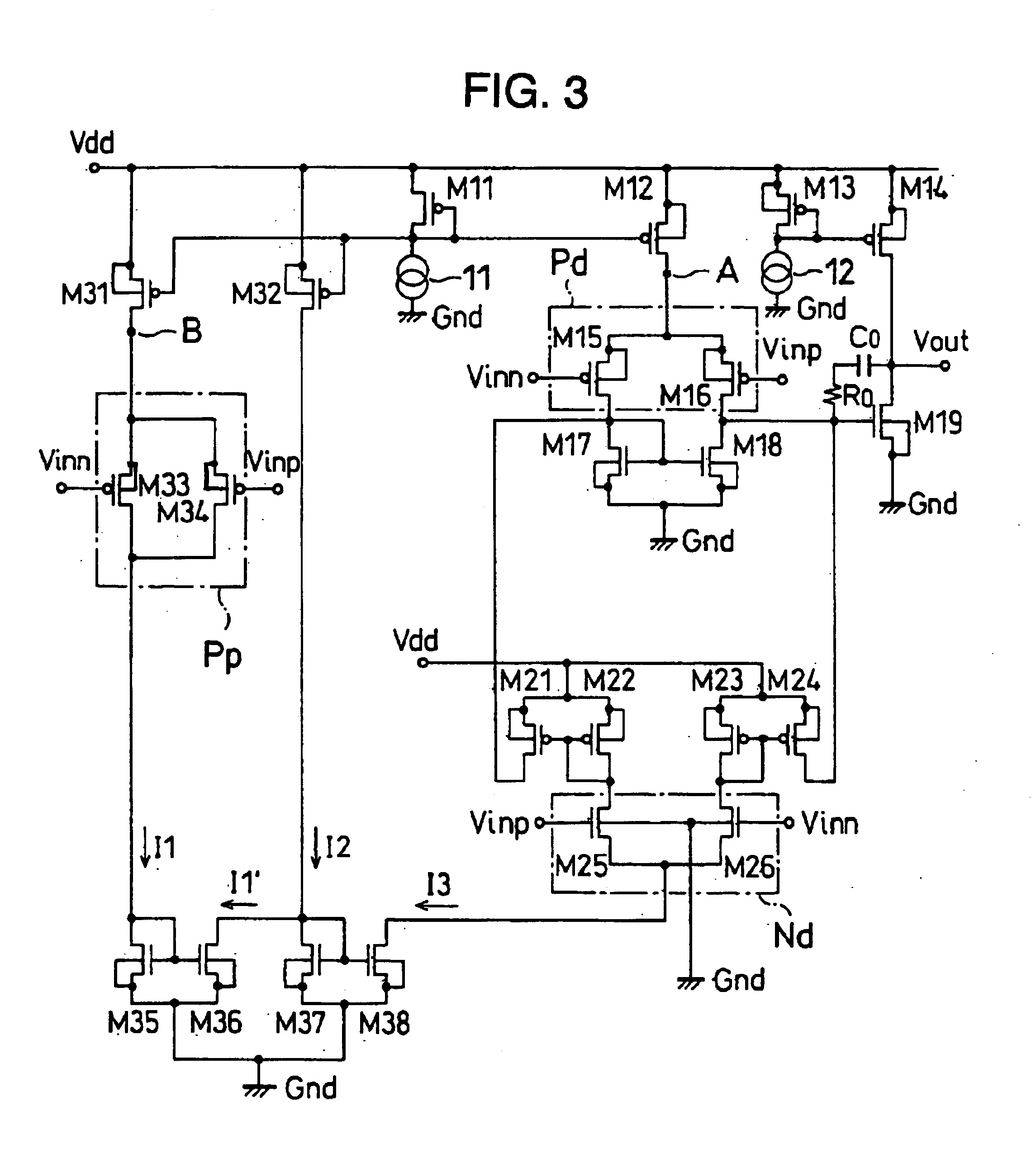
[0038]Referring to FIG. 3, there is shown an operational amplifier according to the invention, constructed in the form of a transistor IC chip.

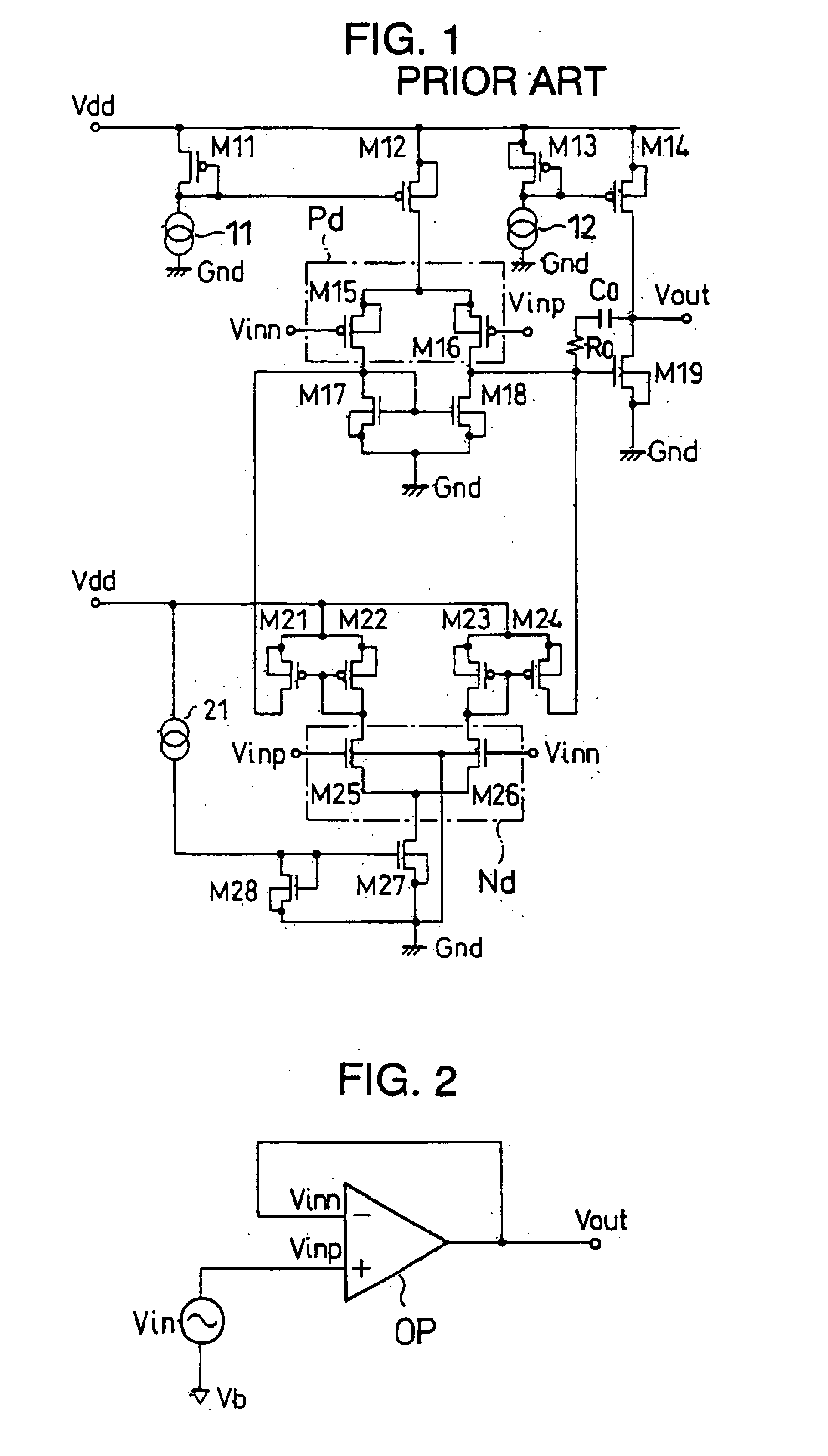
[0039]Like reference numerals in FIGS. 1 and 3 indicate like components. Thus, p-type and n-type transistors M11-M19, constant current sources 11 and 12, condenser Co, resistor Ro, p-type and n-type transistors M21-M26 shown in FIG. 3 are the same as those shown in FIG. 1, and connected in the same way as in FIG. 1.

[0040]N-type transistors M27 and M28 and constant current source 21 of FIG. 1 are deleted from the amplifier shown in FIG. 3.

[0041]On the other hand, p-type and n-type transistors M31-M38 are added to the controller of FIG. 3. The p-type transistors M31 and M32 have their sources connected with the constant voltage source Vdd and gates connected with the drain of the p-type transistor M11 having a constant potential, so that they function as constant current sources. Currents passing through the p-type transistor M31 and the p-type...


PUM


Abstract

An amplifier has a p-type and an n-type difference transistor pairs providing respective outputs, and is adapted to provide the outputs of the pairs in an integrated form. When the level of the input signal is below a predetermined level, only the p-type difference transistor pair is activated, and when the level of the input signal is higher than the predetermined level, the n-type difference transistor pair is also activated. The amplifier has an expanded dynamic range with a suppressed noise level.

Description

[0001]This is a continuation of application Ser. No. 10 / 147,212 filed May 15, 2002, now U.S. Pat. No. 6,759,903, which application is hereby incorporated by reference in its entirety.FIELD OF THE INVENTION[0002]The invention relates to an amplifier having a difference amplification circuit formed on a semiconductor IC chip for amplifying analog signals.BACKGROUND OF THE INVENTION[0003]Current operational amplifiers having a difference amplifier circuit for amplifying analog signals are formed on semiconductor IC chips for use in such audio apparatus as voice codics, Hi-Fi audios, and cellular phones.[0004]In an operational amplifier, a difference amplifier circuit includes a pair of p-channel MOSFETs (hereinafter referred to as p-type transistors) or a pair of n-channel MOSFETs (hereinafter referred to as n-type transistors). However, either type of difference pairs of transistors, incorporating p-type or n-type, has only a limited dynamic range for a given input signal, either in t...

Claims


Application Information

Patent Timeline
IPC IPC(8): H03F3/45H03F3/20H03F3/21H03F1/26H03F3/68
CPCH03F3/21H03F3/45708H03F3/4521
Inventor HORIMOTO, MASASHI
Owner ROHM CO LTD
Why Eureka
Try Eureka