Stereomicroscope

a stereoscopic and microscope technology, applied in the field of stereoscopic microscopes, can solve the problems of main operator not being able to observe the zoomed surgical portion through an optical image, assistant cannot however observe the stereoscopic zoomed surgical portion, etc., and achieves the effect of simple and easy production

Inactive Publication Date: 2008-02-14
MITAKA KOHKI
View PDF5 Cites 11 Cited by
  • Summary
  • Abstract
  • Description
  • Claims
  • Application Information

AI Technical Summary

Benefits of technology

[0014]According to the present invention, since the microscope main body includes therein the objective optical system, the zoom optical system and the eyepiece optical system, the main operator can obtain the pair of optical images including a certain binocular disparity as viewed from the observation direction of the main operator to sterically observe a zoomed surgical portion by his/her naked eyes. Thus, the microscope main body includes only minimum optical systems therein, which allows the configuration of the microscope main body to be simply and e

Problems solved by technology

The assistant can not however observe a stereoscopic zoomed surgical portion because the beam splitter guides only the part of beams into the lateral vision scope.
However, since the s

Method used


Image

  • Stereomicroscope
  • Stereomicroscope
  • Stereomicroscope

Examples


Embodiment Construction

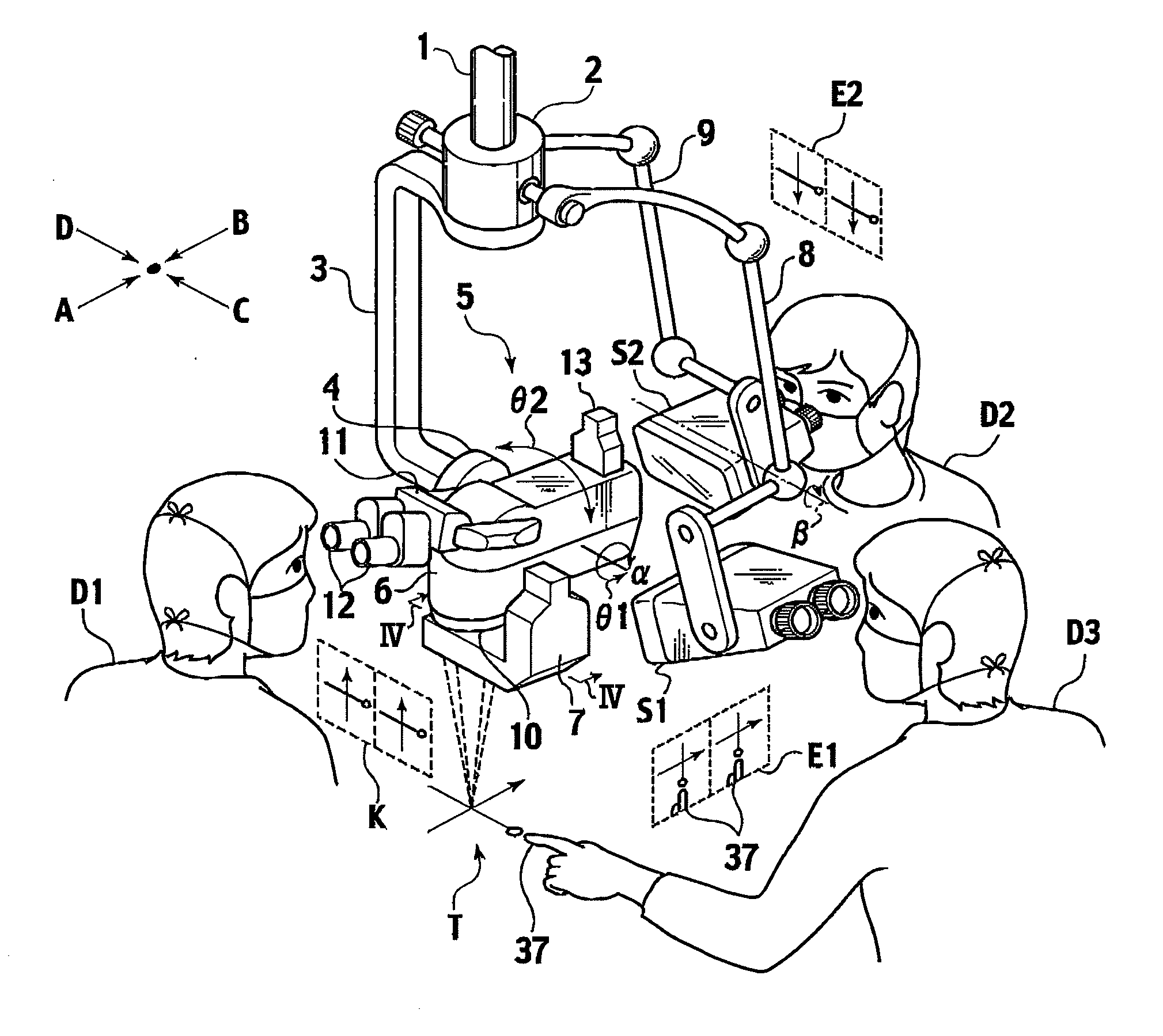
[0023]A stereomicroscope system according to an exemplary embodiment of the present invention will be described below in detail, with reference to FIGS. 1 to 4. In FIGS. 1 and 3, a direction A is an observation direction of a main operator D1. A direction B is opposed to the direction A and an observation direction of an assistant (a person opposed to the main operator D1) D2. In this embodiment, the directions A and B are defined as an anteroposterior direction of the stereomicroscope system. It is noted that the main operator D1 side and the assistant D2 side are a front side and a rear side, respectively. A direction C is positioned at right side with respect to the direction A and orthogonal to the direction A. The direction C is an observation direction of an assistant D3. A direction D is opposed to the direction C and an observation direction of an assistant (a person opposed to the assistant D3) (not shown). In this embodiment, the directions C and D are defined as a horizon...


PUM


Abstract

A stereomicroscope includes a microscope main body and a camera for assistant. The microscope main body includes therein an objective optical system, a zoom optical system and an eyepiece optical system. The camera for assistant is detachably mounted to the microscope main body. The microscope main body provides to a main operator a pair of optical images including a certain binocular disparity as viewed from an observation direction of the main operator. The camera for assistant provides to an assistant a pair of electron images including a certain binocular disparity as viewed from an observation direction of the assistant. The observation directions of the main operator and the assistant cross at a certain angle. The camera for assistant outputs the pair of electron images into a stereo viewer which is separated from the microscope main body.

Description

CROSS-REFERENCE TO RELATED APPLICATION[0001]This application is based upon the prior Japanese Patent Application No. 2006-217083, filed on Aug. 9, 2006, the entire contents of which are Incorporated herein by reference.BACKGROUND OF THE INVENTION[0002]1. Field of the Invention[0003]The present invention relates to a stereomicroscope, and more specifically to a stereomicroscope provided with a camera for assistant which is detachably mounted to the stereomicroscope.[0004]2. Description of the Related Art[0005]A stereomicroscope for use in a cranial nerve surgery or the like introduces beams reflected on a surgical portion into beam introduction holes provided at a lower portion of a microscope main body. The introduced beams are guided to right and left eyes of a main operator through an objective optical system, a zoom optical system and an eyepiece optical system. This allows the main operator to observe a zoomed surgical portion by his / her naked eyes.[0006]The main operator genera...

Claims


Application Information

Patent Timeline
IPC IPC(8): G02B21/18
CPCG02B21/0012G02B21/362G02B21/22
Inventor NAKAMURA, KATSUSHIGE
Owner MITAKA KOHKI
Why Eureka
Try Eureka