Method and system for automated call troubleshooting and resolution

a technology of automated call and troubleshooting, applied in the field of communication networks, can solve problems such as network degradation, packet loss and jitter, and implementations face problems such as latency, packet loss and jitter, and achieve the effect of increasing the overall system availability

Inactive Publication Date: 2008-02-14
RPX CLEARINGHOUSE
View PDF10 Cites 33 Cited by
  • Summary
  • Abstract
  • Description
  • Claims
  • Application Information

AI Technical Summary

Benefits of technology

[0011]The present invention advantageously provides a method and system for call quality troubleshooting and resolution to increase overall system availability. The invention is based on monitoring network performance and using an analysis engine, such as a root-cause analysis (RCA) engine, to detect, correlate and automatically correct the voice and video quality issues.

Problems solved by technology

In general, IP does not provide a mechanism to ensure that data packets are delivered in sequential order, or provide Quality of Service (“QoS”) guarantees, so Voice over IP (“VoIP”) and video over IP (also referred to as “IP streaming video”) implementations face problems dealing with latency, packet loss, and jitter.
One type of latency problem resulting in network degradation is “absolute” or “fixed” delay that can cause a perceived loss of voice / video quality.
Packet loss can be viewed as an extreme case of delay where the packets are so severely delayed that they never arrive.
Additional supported voice and video problems include echo, one way voice path, gaps in speech and distorted / choppy voice / video.
The above described problems may be caused by duplex mismatch, blocked IP packets (due to firewall or network address translation (“NAT”)), congestion, low-speed link in path, fast pipe to slow pipe, route flapping and / or link failure.
Existing voice and video quality management solutions are manual and therefore time-consuming, laborious and prone to error.
In addition, it is nearly impossible for a network administrator to continuously monitor network traffic and also take corrective action in a high availability network environment.

Method used


Image

  • Method and system for automated call troubleshooting and resolution
  • Method and system for automated call troubleshooting and resolution
  • Method and system for automated call troubleshooting and resolution

Examples


Embodiment Construction

[0019]When used herein, the term “trap” is defined to mean a block of data conveyed over a protocol to convey a suboptimal condition and / or a change in condition on some network(s), service(s), device(s) and / or element(s).

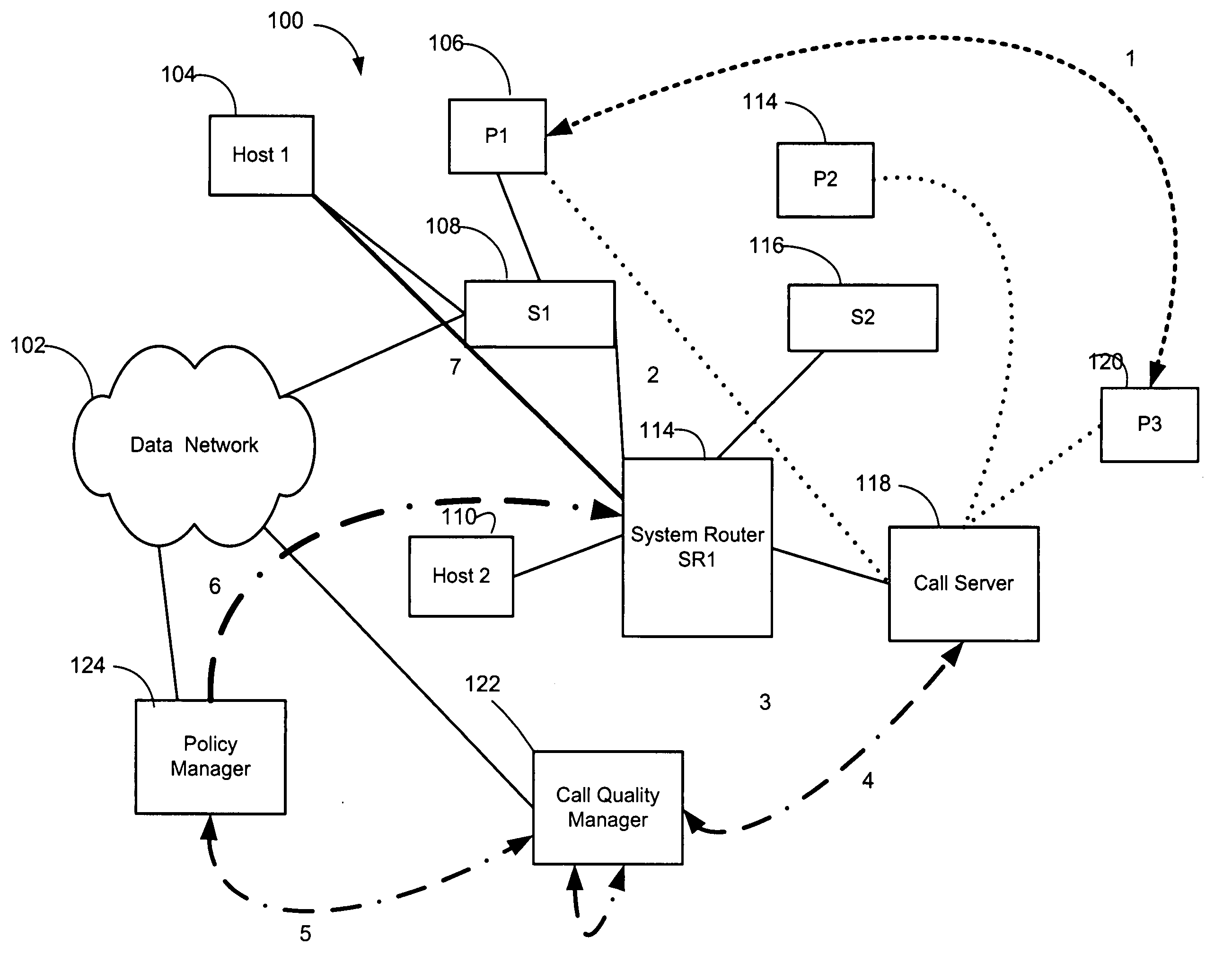
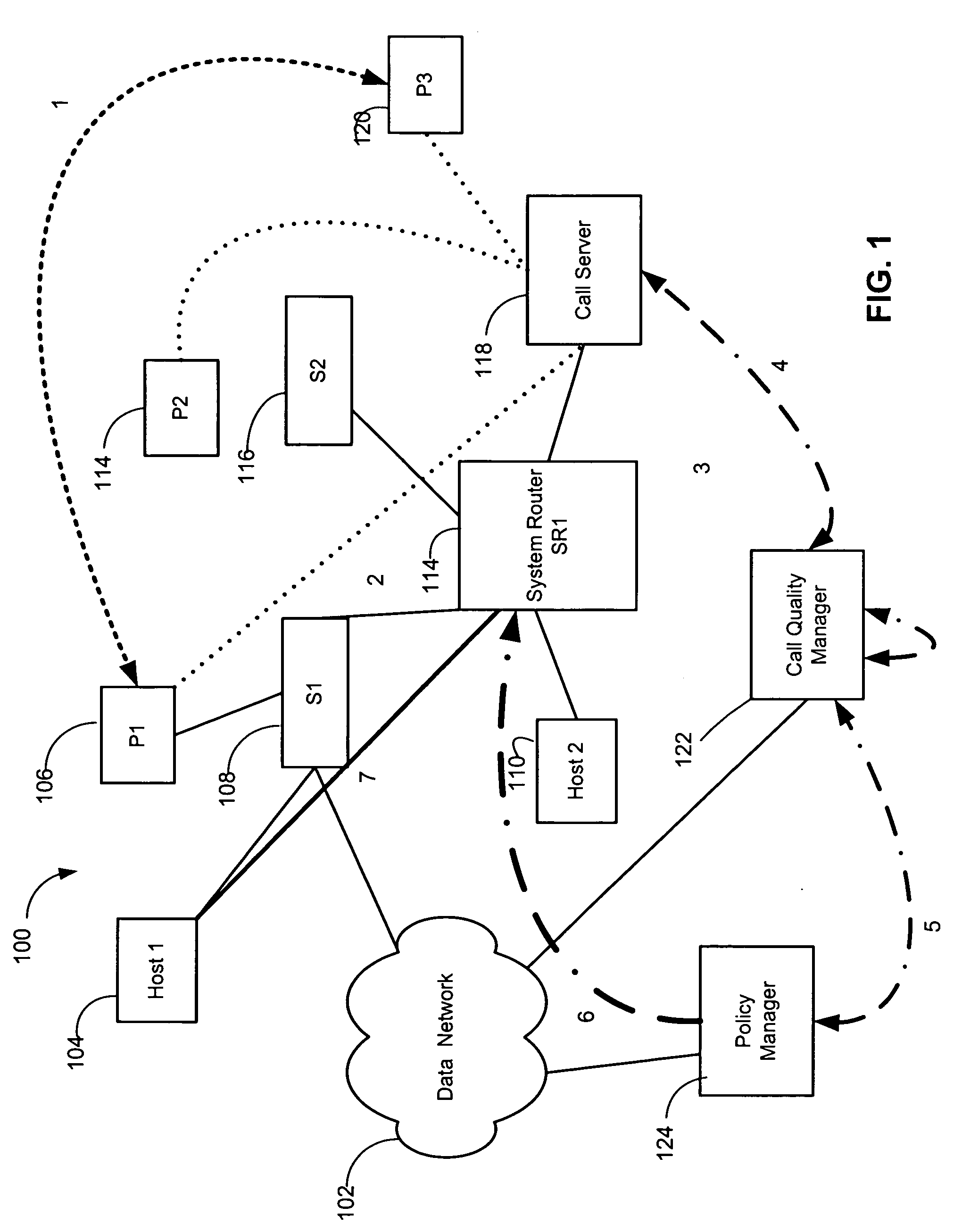
[0020]Referring now to the drawing figures in which like reference designators refer to like elements, there is shown in FIG. 1 a block diagram of a communication system constructed in accordance with the principles of the present invention designated generally by the numeral 100. Communication system 100 preferably includes a data network 102. The data network 102 can be any network having an addressing scheme of various address length and capable of performing the functions herein. For example, an IP routed data network that supports voice and video over IP. The data network 102 is in communication with one or more system switches 108, 116 and one or more system routers 114. Each of the routers 114 includes a central processing unit, volatile and non-volatile sto...


PUM


Abstract

A method and apparatus for call quality troubleshooting and mitigation may include polling network communication path elements to determine network performance data, receiving a call quality alert from at least one communication unit, the call quality alert indicating degraded call quality of a call session, and analyzing the network performance data from the network communication path elements and the at least one communication unit to determine a cause of the alert and at least one action to mitigate the cause of the alert. The apparatus for call quality troubleshooting and mitigation may include a memory for storing data from network communication path elements and data from at least one communication unit, and a processor operating to poll network communication path elements to determine network performance data, to store a call quality alert received from at least one communication unit in the memory, and to the network performance data from the network communication path elements and the at least one communication unit to determine a cause of the alert and at least one action to mitigate the cause of the alert. The method and apparatus may further include correlating the data from the network communication path elements with the data from the at least one communication unit and invoking a real-time network topology investigation module to determine the cause of the call quality alert.

Description

CROSS-REFERENCE TO RELATED APPLICATION[0001]n / aSTATEMENT REGARDING FEDERALLY SPONSORED RESEARCH OR DEVELOPMENT[0002]n / aFIELD OF THE INVENTION[0003]The present invention relates to communication networks and more particularly, to a method and system that provide for automated audio and video call quality troubleshooting and resolution.BACKGROUND OF THE INVENTION[0004]Enterprises of all sizes are expanding Internet Protocol (“IP”) telephony and IP video deployments such that what is traditionally thought of as separate voice, video and data networks are converging to run over an IP infrastructure. Even though voice and video are sometimes characterized as just other applications, the fundamental aspects of voice / video conversations place requirements on the network that are quite different from data applications. These requirements amount to providing toll quality voice (and video), which is measured in terms of clarity and delay. Unlike data applications in which automatic retransmis...

Claims


Application Information

Patent Timeline
Patent Type & Authority Applications(United States)
IPC IPC(8): H04L12/28
CPCH04M3/2227H04L65/80
Inventor ANSARI, ZUBAIRTESTER, WALTER SCOTTPENDLETON, AMYPALAPARTHI, RAVISHANKARLI, JENNYGHOSH, PARAMA
Owner RPX CLEARINGHOUSE
Why Eureka
Try Eureka