
Needle with depth determination capability and method of use

a technology of depth determination and needle, which is applied in the field of needle with depth determination capability and method of use, can solve the problems of difficulty in single operator needle placement and positioning in patient, difficulty in insertion and positioning of needle in patient, and difficulty in a single user to accomplish, so as to accurately position the needle and reduce the cost. the effect of the cos

Inactive Publication Date: 2008-02-14
NERVONIX INC
View PDF2 Cites 57 Cited by
  • Summary
  • Abstract
  • Description
  • Claims
  • Application Information

AI Technical Summary

Benefits of technology

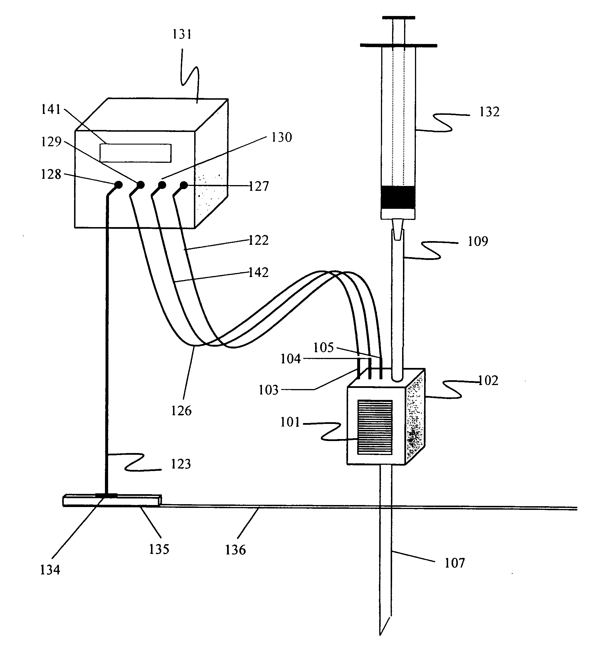
[0011]In accordance with the present invention, an output control needle comprising an insulated hypodermic needle having a means for fingertip control of the stimulator output current and a means of depth determination. The invention will provide a means for a single operator, the anesthetist, to accurately position a needle and perform a regional anesthetic technique without need of an assistant or excessive cabling. This further reduces the costs associated with an assistant's time while maintaining operating room hazards at a minimum.
[0012]It is an object of the present invention to provide a nerve stimulator needle with fingertip control of output current, which avoids the need for an assistant or foot pedal to adjust the output source during the performance of a regional anesthetic procedure.

Problems solved by technology

Stimulators that are manufactured specifically for regional anesthesia applications typically do not have frequency options greater than 5 Hz.
This is awkward for a single user to accomplish and usually requires the presence of an assistant.
In this method, it is difficult for a single operator to insert and position the needle in the patient, control the current supplied the nerve stimulator needle, and inject the medication in the patient.
In the environment of an operating room where a multiplicity of electrical cables already exists, any equipment that adds additional cables spread out across the floor or tables and carts represents increased hazard for stumbling and consequent injury.
Tangles of cables and wires complicate this process and have a tendency to increase the clutter surrounding anesthesia machines and carts.
As the entire nerve stimulator device is clamped onto the syringe, the unit is a long and clumsy assembly, which is difficult to maneuver.
Moreover, the device disclosed by Chester does not allow for one-handed operation of needle advancement and current control.
Particularly, the needle is advanced by one hand while the current must be controlled by turning the knob 27 with the other hand, which is an extremely awkward operation for the user.
Additionally, the nerve stimulator of the Chester patent restricts the size of the syringe upon which it may be mounted, thus, requiring the operator to change the syringe on the needle.
This combination makes it very difficult to stabilize the needle within 1-2 mm of a nerve as desired for a regional block.
Like the Chester patent, the system of Blumenfeld also does not allow for one-handed operation of both needle advancement and current control.
Accordingly, the system of the Blumenfeld patent also provides a clumsy operation for the user.
Displacement may be due to inadvertent pressure applied by the operator, or the tendency of the injected fluid to force the needle back along its tissue track.
At present, there is no mechanism for providing such information with the currently available needles designed for use with nerve stimulators.

Method used


Image

  • Needle with depth determination capability and method of use
  • Needle with depth determination capability and method of use
  • Needle with depth determination capability and method of use

Examples


Embodiment Construction

[0041]Reference will now be made in detail to the present preferred embodiment of the invention, an example of which is illustrated in the accompanying drawings.

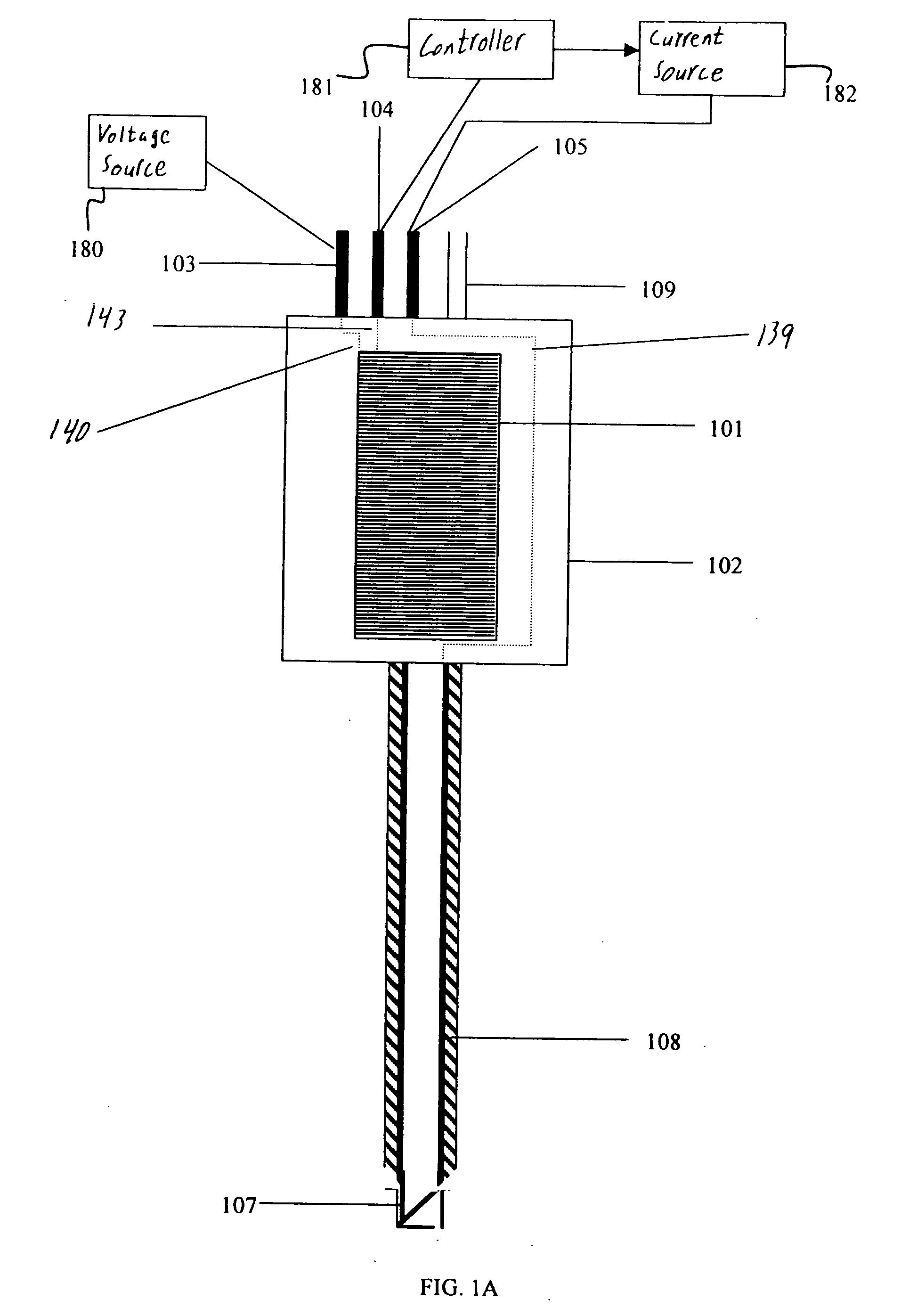
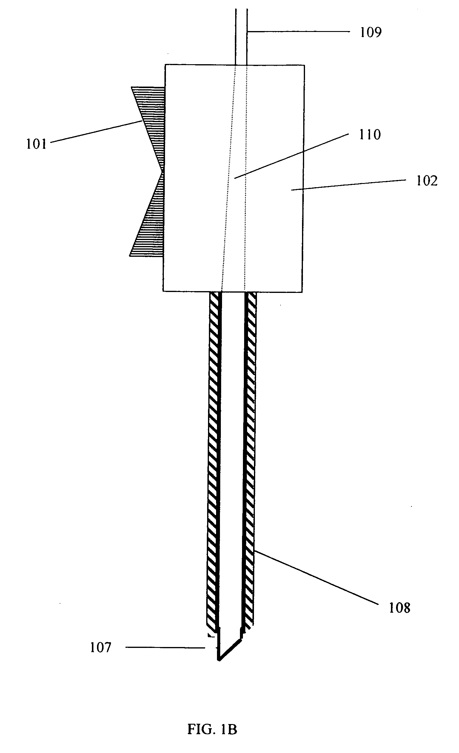
[0042]A preferred embodiment of the present invention comprises a nerve stimulator function that allows control of the current output through a fingertip control on the stimulating needle. A preferred embodiment of the needle assembly of the present invention is illustrated in FIG. 1A (front view) and FIG. 1B (side view). A needle assembly consists of a housing unit 102. The housing unit may be made of any suitable material such as molded plastic. The housing unit 102 preferably contains a plurality of electrical pin connectors 103, 104 and 105 that electrically connect the housing unit 102 to an external nerve stimulator device or a plurality of external devices. Electrical traces 139, 140, and 143 are preferably embedded within the housing unit 102 and are electrically connected to a corresponding electrical pin connector....


PUM


Abstract

A needle apparatus capable of measuring the depth of the needle in tissue of a patient includes a linear resistive coating on the needle. Resistance of the resistive layer changes with the length of the resistive layer. The depth of the needle in tissue is determined by measuring the resistance of the length of the needle above the skin surface of the patient.

Description

RELATED APPLICATIONS[0001]This application is a continuation-in-part of U.S. patent application Ser. No. 10 / 772,397, filed on Feb. 5, 2004 which is a divisional of U.S. patent application Ser. No. 09 / 989,206 filed on Nov. 21, 2001, now U.S. Pat. No. 6,706,016 issued Mar. 16, 2004, which claims priority to U.S. provisional application 60 / 253,064 filed on Nov. 24, 2000, each of the contents of which are herein incorporated by reference.TECHNICAL FIELD[0002]This invention relates to a nerve-stimulating needle with fingertip control of stimulator current output and visual as well as electrical depth determination ability.BACKGROUND OF THE INVENTION[0003]Anesthesiologists commonly use nerve stimulators and insulated needles for the purpose of locating peripheral nerves, or nerve plexuses, for the performance of regional anesthesia procedures. This procedure is discussed in Vloka J D et al., “A National Survey On Practice Patterns In The Use Of Peripheral Nerve Stimulators In Regional Ane...

Claims


Application Information

Patent Timeline
Patent Type & Authority Applications(United States)
IPC IPC(8): A61N1/00
CPCA61N1/36014A61N1/0551
Inventor CORY, JOAN M.CORY, PHILIP C.
Owner NERVONIX INC
Learn More