
Lead set for nerve stimulator and method of operation thereof

Active Publication Date: 2008-02-14
UROPLASTY
View PDF31 Cites 46 Cited by
  • Summary
  • Abstract
  • Description
  • Claims
  • Application Information

AI Technical Summary

Problems solved by technology

However, transcutaneous stimulators often require higher current levels than percutaneous and implantable stimulators.
Higher current levels can cause irritation and discomfort when used for extended periods.
Thus, transcutaneous stimulators may not be highly effective for direct nerve stimulation.
However, implantable stimulators can cause mild discomfort, and often cause more severe implant-site pain.

Method used


Image

  • Lead set for nerve stimulator and method of operation thereof
  • Lead set for nerve stimulator and method of operation thereof
  • Lead set for nerve stimulator and method of operation thereof

Examples


Embodiment Construction

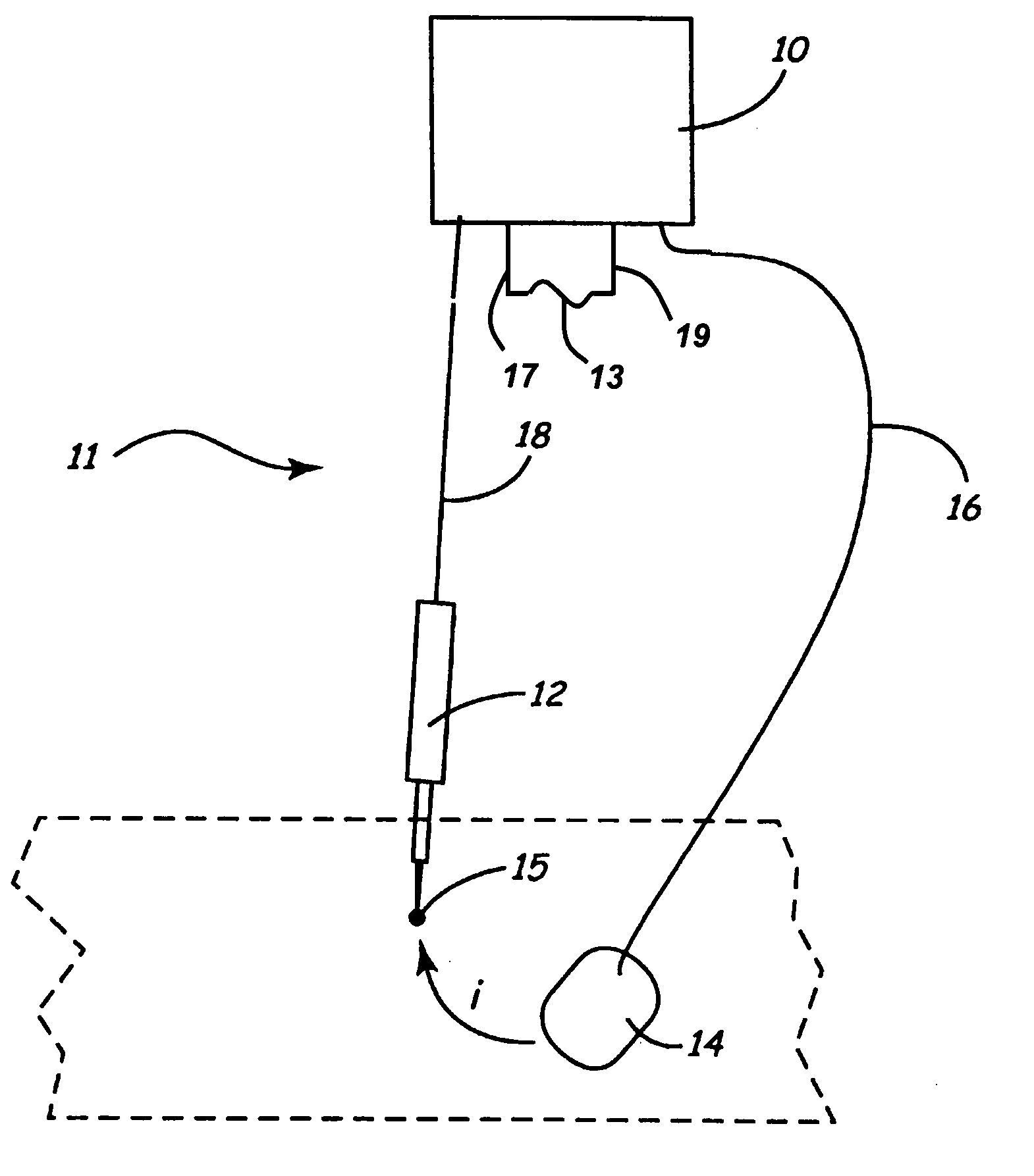
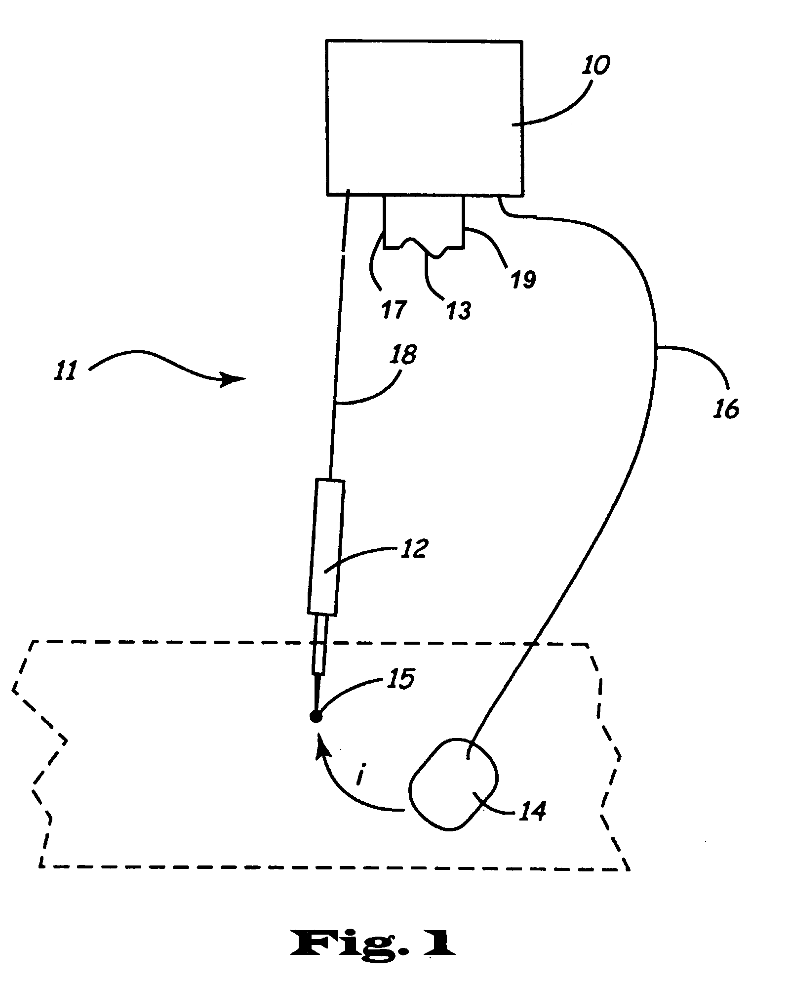
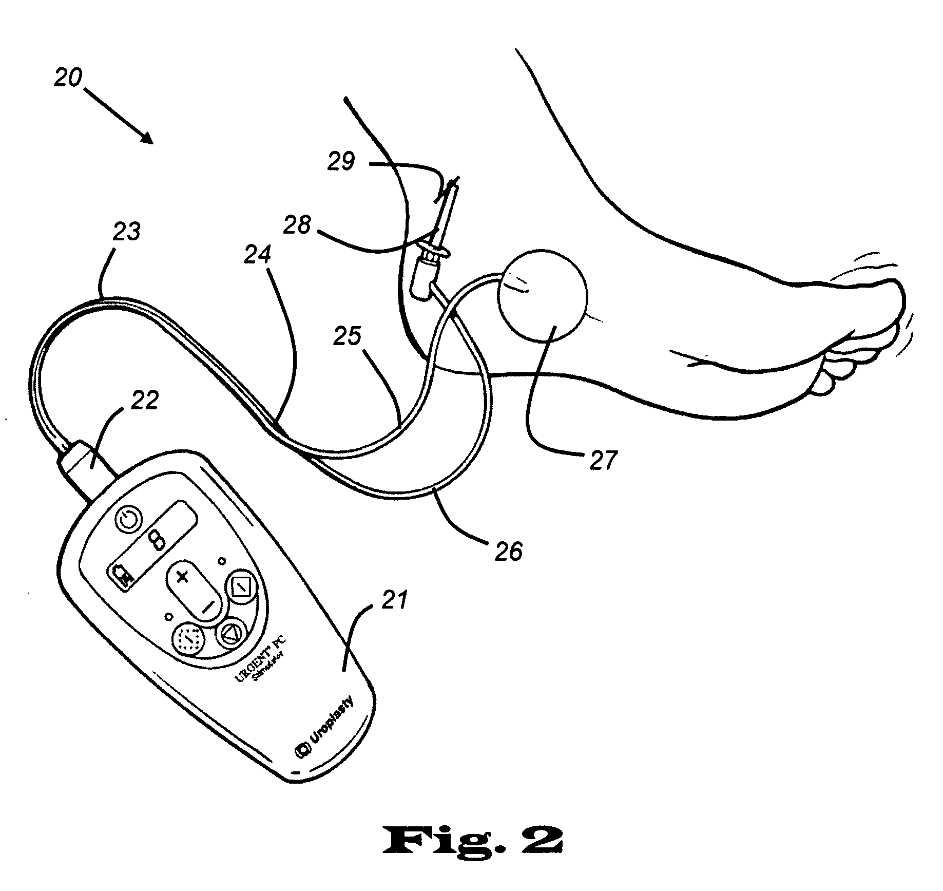
[0027] Nerve and muscle stimulation may be used by medical providers to treat a variety of ailments. For instance, urinary incontinence may be treated by stimulating the sacral nerves, which affect bladder control. One such treatment may be done in a percutaneous manner by inserting a fine gauge needle into the posterior tibial nerve just above the ankle and applying an electrical stimulation to the needle. The tibial nerve carries the electrical stimulation up the leg to the S3 region of the lower spinal cord. Electrical stimulation near the S3 region is effective in treating chronic pelvic pain, fecal incontinence, nocturnal urinary frequency, interstitial cystitis symptoms of urinary frequency, urinary urgency, and urinary urge incontinence, and overactive bladder symptoms of urinary frequency, urinary urgency and urinary urge incontinence.

[0028] An example of an electrical nerve stimulator is disclosed in U.S. Pat. No. 6,493,588 entitled “Electro-nerve stimulator systems and me...


PUM


Abstract

Single-use electrical leads for a nerve stimulator are disclosed. The leads include a status flag element such as a fuse, which is deliberately blown after use of the leads has begun to indicate that the leads are not to be reused. The nerve stimulator has a “test mode” that determines a current value for treatment, and a “therapy mode” that administers treatment with the chosen current value. If the fuse in the electrical leads is blown (not conducting), then the stimulator assumes that the leads have already been used and does not enter therapy mode, and optionally may not enter test mode. If the fuse in the electrical leads is intact (conducting), or not blown, then the stimulator assumes that the leads are as yet unused, and allows the user to enter either test mode or therapy mode. The fuse is deliberately blown after a particular amount of time spent in therapy mode. After the fuse is blown, the user may still complete the therapy mode, even though the fuse is non-conducting, although the user may not initiate another therapy mode (and optionally may not initiate another test mode) using the blown leads. Preferably the fuse is electrically isolated from the leads that contact the patient.

Description

CROSS-REFERENCE TO RELATED APPLICATIONS [0001] This application claims the benefit of U.S. Provisional Patent Application Ser. No. 60 / 801,589 filed May 18, 2006, which hereby is incorporated herein in its entirety by reference thereto. This application is a continuation-in-part of and claims the benefit of U.S. patent application Ser. No. 10 / 492,578 filed Sep. 13, 2004, which hereby is incorporated herein in its entirety by reference thereto, and which is National Stage Entry of PCT / US02 / 33318 filed Oct. 18, 2002, which claims the benefit of U.S. Provisional Patent Application Ser. No. 60 / 336,074 filed Oct. 18, 2001.STATEMENT REGARDING FEDERALLY SPONSORED RESEARCH OR DEVELOPMENT [0002] Not Applicable BACKGROUND OF THE INVENTION [0003] 1. Field of the Invention [0004] The present invention is directed to nerve stimulators, and more particularly to electrical leads for nerve stimulators and methods of operation thereof. [0005] 2. Description of the Related Art [0006] Physical therapis...

Claims


Application Information

Patent Timeline
IPC IPC(8): A61N1/02
CPCA61N1/0492A61N1/0502A61N1/0456A61N1/36021A61N1/3752A61N1/0551A61N1/3603
Inventor VAN DEN BIGGELAAR, JOHANNES F.M.WILLIAMS, JEFFREY M.HERREGRAVEN, MARC M.SANDSTROM, PAUL EDWARDSCHAUER, ANTHONY W.
Owner UROPLASTY
Learn More