Heat Exchanger

Inactive Publication Date: 2008-02-21
KEIHIN THERMAL TECH CORP
View PDF7 Cites 15 Cited by
  • Summary
  • Abstract
  • Description
  • Claims
  • Application Information

AI Technical Summary

Benefits of technology

[0033] With the heat exchanger of par. 10), while an increase in air flow resistance is suppressed, heat exchange performance is improved, thereby establishing good balance therebetween.
[0034] With the heat exchanger of par. 11), while an increase in air flow resistance is suppressed, heat exchange performance is improved, there

Problems solved by technology

However, various studies conducted by the present inventors have revealed that enhancing heat exchange performance to a higher level is difficult for the evaporator described in the above-mentioned publication, for the reason described below.
However, since the overall internal volume of the refrigerant inlet header section with which the heat exchange tubes communicate becomes large, response tends to become slow, particularly, at the time of on-off

Method used


Image

  • Heat Exchanger
  • Heat Exchanger
  • Heat Exchanger

Examples


Embodiment Construction

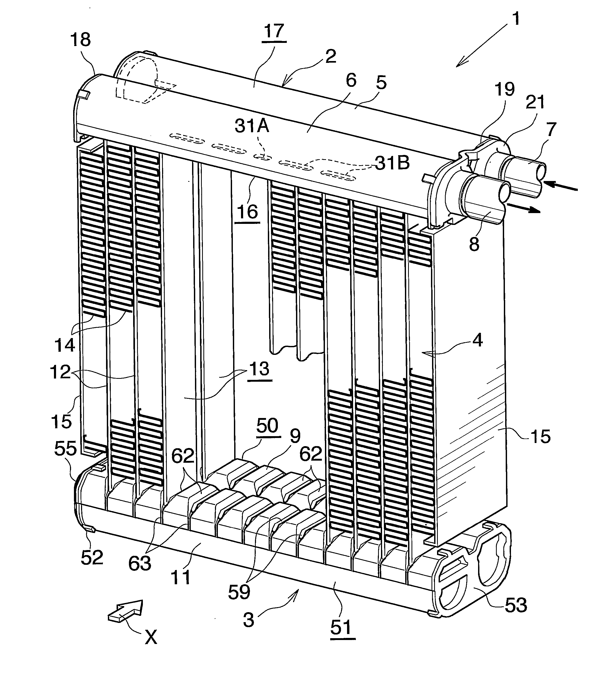
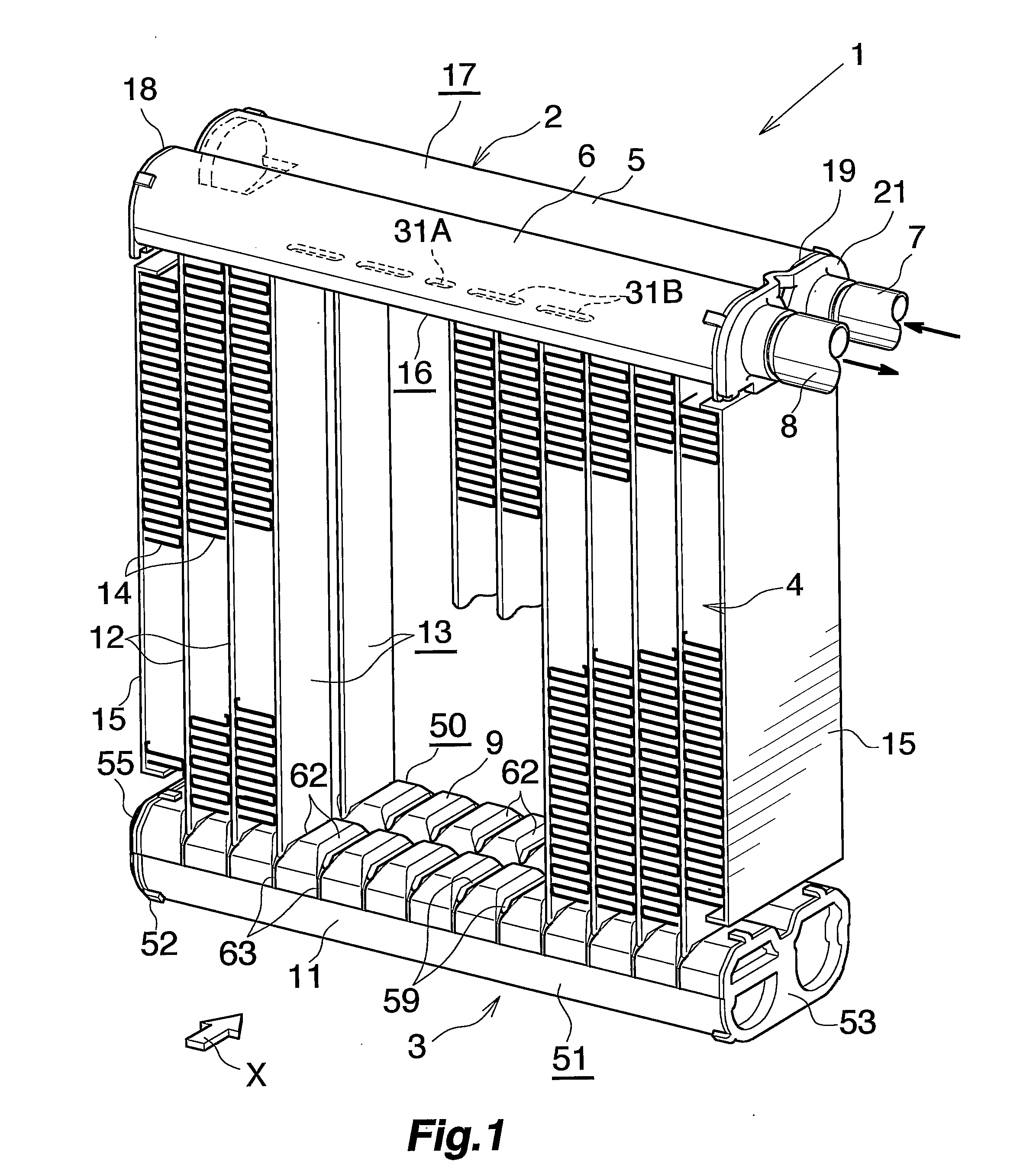
[0050] An embodiment of the present invention will next be described in detail with reference to the drawings. The embodiment is of a heat exchanger according to the present invention that is applied to an evaporator of a car air conditioner using a chlorofluorocarbon-based refrigerant.

[0051] In the following description, the upper, lower, left-hand, and right-hand sides of FIGS. 1 and 2 will be referred to as “upper,”“lower,”“left,” and “right,” respectively.

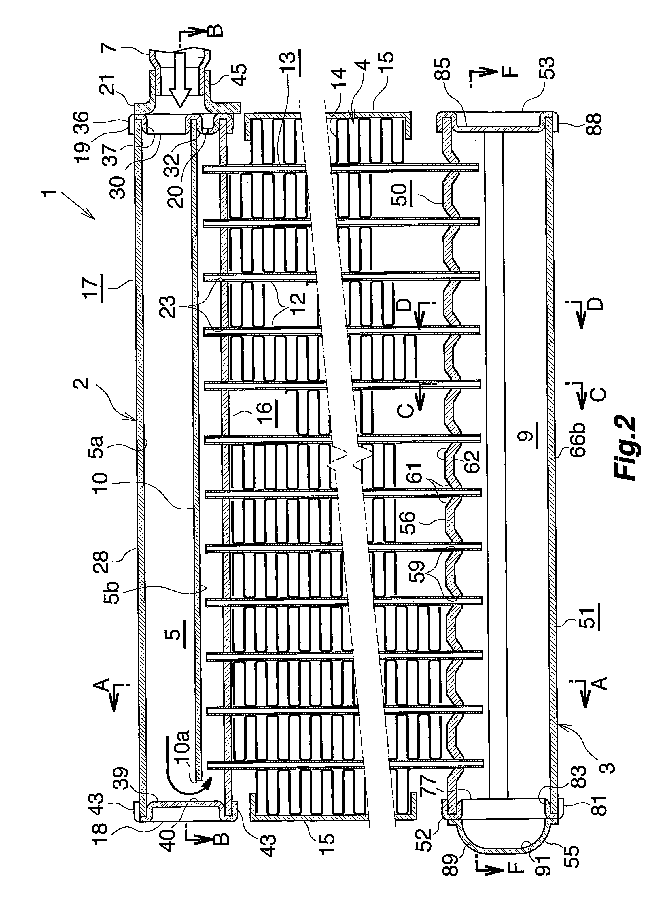
[0052] FIGS. 1 to 3 show the overall configuration of an evaporator, and FIGS. 4 to 12 show the configuration of essential portions of the evaporator. FIG. 13 shows how a refrigerant flows in the evaporator.

[0053] In FIG. 1, the evaporator (1) includes a refrigerant inlet / outlet header tank (2) made of aluminum, a refrigerant turn header tank (3) made of aluminum, and a heat exchange core section (4) provided between the header tanks (2) and (3).

[0054] The refrigerant inlet / outlet header tank (2) includes a refrigerant inle...


PUM


Abstract

An evaporator includes a refrigerant inlet header section having a refrigerant inlet at a first end portion thereof and plural heat exchange tubes disposed at predetermined intervals in the longitudinal direction of the refrigerant inlet header section and connected at respective first end portions thereof to the refrigerant inlet header section. A flow-dividing control wall divides the refrigerant inlet header section interior into an upper space, into which a refrigerant flows through the refrigerant inlet, and a lower space, with which the heat exchange tubes communicate. A communication hole in the flow-dividing control wall at an end portion opposite the first end portion establishes communication between the spaces therethrough. A flow-division-adjusting hole communicating with the lower space formed at the first end portion of the refrigerant inlet header section allows the refrigerant to flow into the lower space therethrough without passing through the upper space.

Description

CROSS REFERENCE TO RELATED APPLICATIONS [0001] This application is an application filed under 35 U.S.C. § 111(a) claiming the benefit pursuant to 35 U.S.C. § 119(e)(1) of the filing date of Provisional Application No. 60 / 632,985 filed Dec. 6, 2004 pursuant to 35 U.S.C. § 111(b).TECHNICAL FIELD [0002] The present invention relates to a heat exchanger, and more particularly to a heat exchanger preferably used as an evaporator of a car air conditioner, which is a refrigeration cycle to be mounted on, for example, an automobile. [0003] Herein and in the appended claims, the term “aluminum” includes aluminum alloys in addition to pure aluminum. Also, herein and in the appended claims, the downstream side (a direction represented by arrow X in FIG. 1) of an air flow through air-passing clearances between adjacent heat exchange tubes will be referred to as the “front,” and the opposite side as the “rear.”BACKGROUND ART [0004] Conventionally, a so-called laminated evaporator has been widely...

Claims


Application Information

Patent Timeline
IPC IPC(8): F25B39/02
CPCF25B39/02F28F9/0278F28F9/0214F28D1/05391
Inventor HIGASHIYAMA, NAOHISA
Owner KEIHIN THERMAL TECH CORP
Why Eureka
Try Eureka