Coiled tubing well tool and method of assembly

Inactive Publication Date: 2008-02-21
CONOCOPHILLIPS CO
View PDF7 Cites 48 Cited by
  • Summary
  • Abstract
  • Description
  • Claims
  • Application Information

AI Technical Summary

Benefits of technology

[0012]The actual position within the housing of each element is determined from the outside of the housing and each element (e.g. sensor) is then secured to the housing at that position by any appropriate means, e.g. dimpling the housing at each element location. The housing, if not already a part of the lower end of the coiled tubing string, is attached to the coiled tubing string and effectively becomes an “integral” part of the “spoolable” string.
[0013]By effectively inco

Problems solved by technology

Not only is this operation time consuming, it can also lead to inaccuracies in the final log since, in many instances, it is critical not only to know the depth at which each measurement is taken but also the exact distances between the respective measurement points.
However, since the sensors are fixed in a rigid cylindrical housing (e.g. length of pipe, casing, or the like), the number of sensors that can be mounted in the rigid housing is limited since the overall length of the tool (i.e. housing) has to be kept relatively short in order to transverse deviated and horizontal wellbores typically encountered during the logging operatio

Method used


Image

  • Coiled tubing well tool and method of assembly
  • Coiled tubing well tool and method of assembly
  • Coiled tubing well tool and method of assembly

Examples


Example

[0017]While the invention will be described in connection with its preferred embodiments, it will be understood that this invention is not limited thereto. On the contrary, the invention is intended to cover all alternatives, modifications, and equivalents that may be included within the spirit and scope of the invention, as defined by the appended claims.

DESCRIPTION OF THE PREFERRED EMBODIMENTS

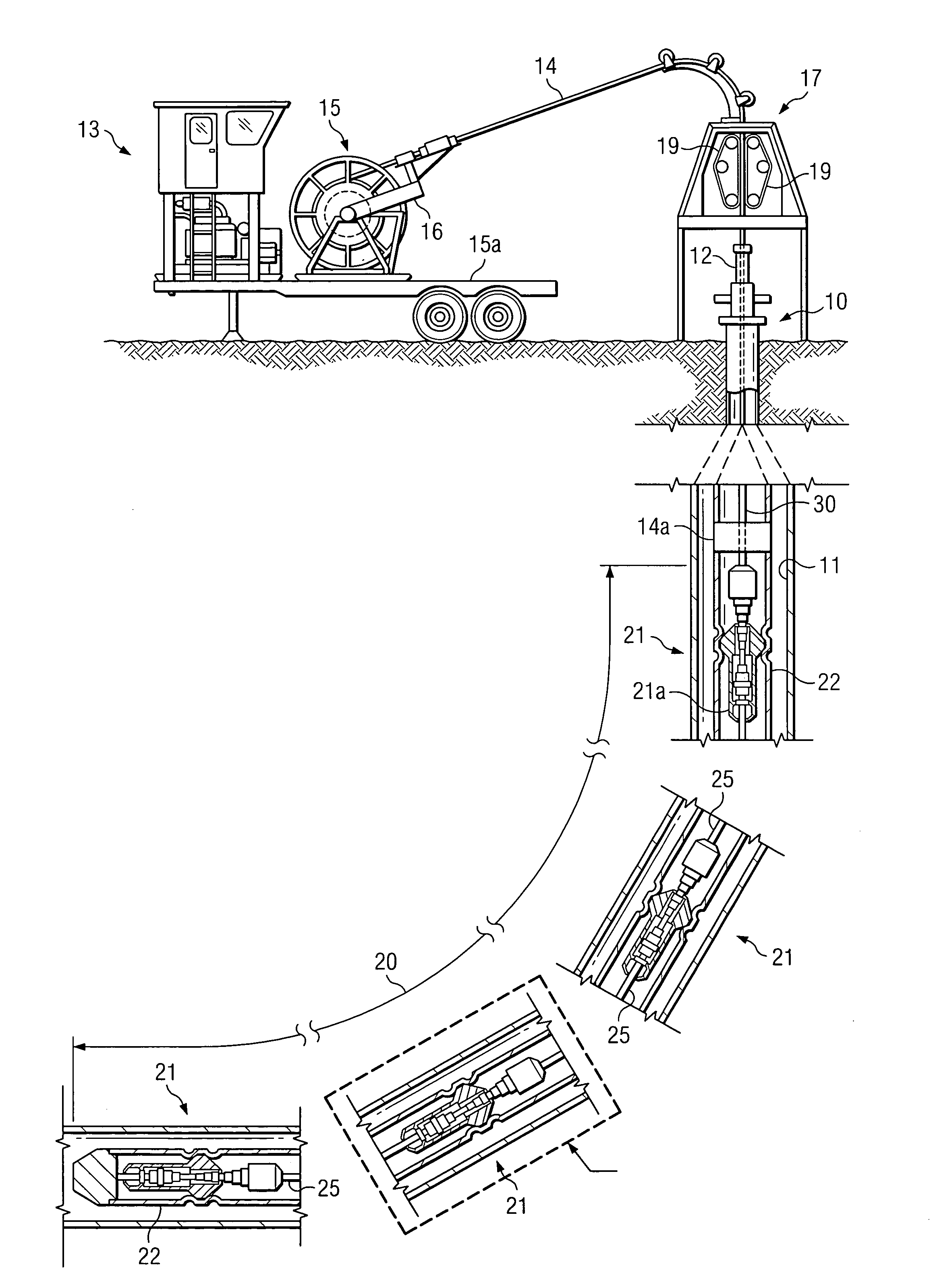
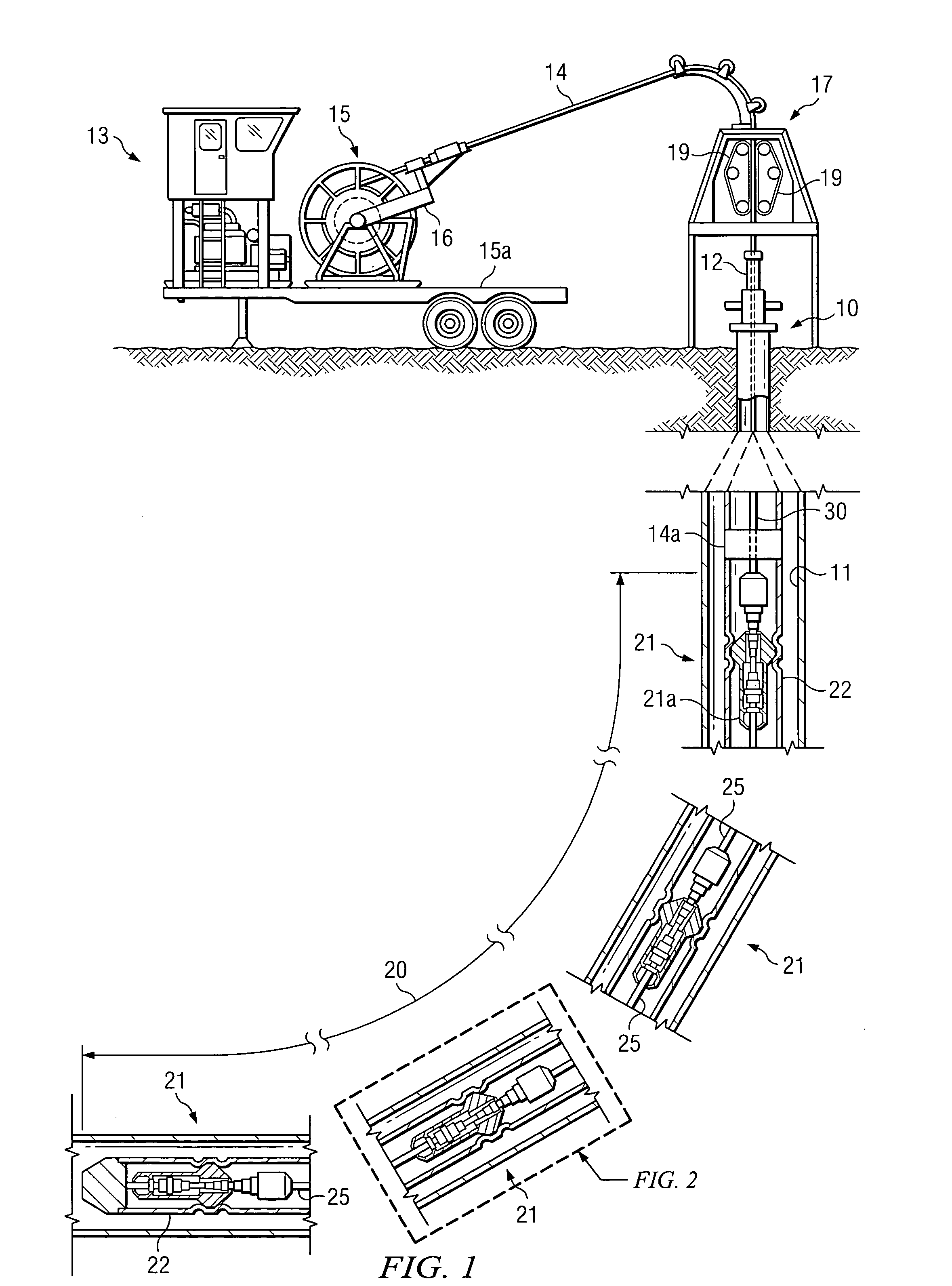
[0018]Referring now to the drawings, FIG. 1 illustrates a well 10 having a wellbore 11 and a wellhead 12. As will be understood, wellbore 11 can be cased (as shown), lined, open, or otherwise completed and can be vertical, slanted, and / or horizontal. A typical, coiled tubing system 13 is positioned on the surface for running a coiled tubing string 14 into and out of the wellbore 11 through wellhead 12. As will be understood in the art, the term “coiled tubing”, as used herein is a continuous length of a relatively small diameter (up to 6 inches), thin-walled relatively flexible metal tubing (...


PUM


Abstract

A long, well tool which effectively performs as an integral part of a typical coiled tubing string and accordingly can be ran continuously into a pressurized wellbore with the same deployment equipment as used with known coiled tubing. The tool is comprised of a plurality of elements (e.g. perforating charges or logging sensors such as hydrophones, geophones, gamma ray sensors, gravity sensors, etc.) fixed at spaced, known distances from each other within a flexible housing, e.g. a length of coiled tubing.

Description

1. TECHNICAL FIELD[0001]The present invention relates to a downhole well tool which is effectively incorporated into the lower end of a string of coiled tubing and in one of its aspects relates to running a long well tool having a plurality of elements (e.g. logging sensors, perforating charges, etc.) into a pressurized wellbore without the need of specialized, pressure deployment equipment or procedures.2. BACKGROUND OF THE INVENTION[0002]It has long been routine to run a long well tool into a wellbore to carry out a particular operation. For example, it is routine to “log” a well after or during drilling to determine various characteristics of the subterranean formations traversed by the wellbore. That is, a well may be logged to determine the presence and location of any oil / gas deposits that may lie adjacent the wellbore. Some of these logging operations require taking measurements at several spaced points within the wellbore and then collating the collected data to produce the ...

Claims


Application Information

Patent Timeline
IPC IPC(8): E21B19/16E21B43/00
CPCE21B17/20E21B43/00E21B23/14E21B19/22
Inventor BLOUNT, CURTIS G.BRADY, JERRY L.
Owner CONOCOPHILLIPS CO
Why Eureka
Try Eureka