Valve mechanism for tube-type fluid container

a valve mechanism and fluid container technology, applied in the field of valve mechanisms, can solve the problems of deteriorating the quality of the fluid stored in the fluid storage portion, low durability, and high manufacturing cost of the valve mechanism using the spherical valve body and the spring, and achieve the effect of reliably closing the fluid

Inactive Publication Date: 2008-02-21
MASUDA MASATOSHI
View PDF0 Cites 22 Cited by
  • Summary
  • Abstract
  • Description
  • Claims
  • Application Information

AI Technical Summary

Benefits of technology

[0019] The present invention solves the above-mentioned problems. It aims to provide a valve mechanism which can close a fluid reliably while its configuration is simple and which can alter a flow rate of the fluid passing through the valve mechanism discretionally according to a pressure applied to the fluid.
[0035] In the above, the fluid can be discharged from an outlet of the mouth portion of the container through the valve mechanism by pressing the container, wherein the connectors and the container are deformed. When releasing the pressure, both the deformed connectors and the deformed container begin restoring the shapes. The restoring force of the container causes the inner pressure to lower, thereby generating reverse flow which facilitates restoration of the connectors to close the opening of the valve seat portion, thereby effectively preventing air from coming into the container through the outlet of the mouth portion. Thus, even if the restoring force of the connectors themselves is not sufficient to close the opening of the valve seat portion, the outlet of the mouth portion can effectively be closed in combination with the restoring force of the container. Thus, even if the fluid is very viscous, the valve mechanism in combination with the container can discharge the fluid and then seal the container.
[0039] In the above, in the event that the restoring force of the container is excessive (depending on the viscosity of the fluid and the amount of the fluid remaining in the container, etc., in addition to the elasticity characteristics of the container itself), the reverse flow is strong and fast, and the connectors may not be restored so quickly that it is difficult to prevent air from coming into the container from the outlet of the mouth portion through the opening of the valve seat portion. In that case, by using a double wall container, the restoring force can be controlled so that intensity of the reverse flow can be controlled to prevent air from coming into the container.
[0041] Additionally, in a double wall container, restoring force of an inner container may be lower than that of a single wall container, and thus, after connectors are at a closed position, the pressure inside the inner container may remain moderately lower than the ambient pressure, so that suction force at the outlet may not be significant. In that case, it is possible to effectively prevent air from coming into the container. Further, in a double wall container, an outer container can be restored more than an inner container, and an air layer is formed between the inner container and the outer container. When restricting the flow of air released from the air layer through a through-hole or though-holes, it is possible to exert pressure on the inner container from the outer container via the air layer. Thus, even if the amount of the fluid contained in the inner container is low and thus, the inner container is nearly flat, by pressing the outer container which has been restored to the original shape, it is possible to exert pressure onto the inner container, thereby easily discharging the fluid. Accordingly, waste of the fluid remaining inside the inner container can be minimized.

Problems solved by technology

Manufacturing costs of the valve mechanism using the spherical valve body and the spring, however, tend to be high.
In the case of a tube-type container using a synthetic-resin-made tube, because these synthetic-resin-made tubes have an elasticity recovering force, the following problem occurs: When a pressure is removed after a fluid is discharged by applying the pressure to the tube, the air flows back from an opening portion for discharging the fluid to the fluid storing portion by the elasticity recovering force of the tube, deteriorating the quality of the fluid stored in the fluid storing portion.
Additionally, the conventional tube-type container in which the above-mentioned tabular valve body is provided has a problem that its durability is low.
Consequently, as the content remaining in the tube-type container is reduced, a shape change of the container increases and it becomes harder to discharge the content from the tube-type container.
The tube-type container described in Japanese Patent Laid-open No. 2000-109103, however, can be used only with high-viscosity contents, because it does not possess a valve mechanism at its discharge port.
If a low-viscosity fluid is stored in this tube-type container, there is a problem that the air flows back into the container from the discharge port of the container, lowering the quality of the fluid stored in the container.
The valve mechanism, however, is generally expensive and increases the manufacturing costs of the tube-type container which should be manufactured inexpensively because it is disposable under normal conditions.
It is difficult, however, to manufacture a tube-type container with a valve construction portion provided at its body portion.
Additionally, there is a problem that welding cannot be done satisfactorily due to the valve construction portion when attempting welding the bottom portion of the tube-type container.

Method used


Image

  • Valve mechanism for tube-type fluid container
  • Valve mechanism for tube-type fluid container
  • Valve mechanism for tube-type fluid container

Examples


embodiment 2

[0120] A construction of a tube-type fluid container according to another embodiment of the present invention is described below. FIG. 5 is an exploded longitudinal section of the tube-type fluid container according to the

[0121] In the above-mentioned tube-type container according to the Embodiment 1, the lid material 2 having a construction in which with the female screw portion 222 of the lid material screwing together with the male screw portion 14 in the container main unit, the discharge port 12 of the container main unit 1 is closed, is used. In this Embodiment 2, a lid material 4 having a fluid discharge port 241 at its end is used. The fluid container according to the Embodiment 2 has a construction in which a discharge port 12 of the container main unit 1 and the discharge port 241 of the lid material 4 are communicated with the female screw portion 242 of the fluid container screwing together with the male screw portion 14 of the container main unit 1.

embodiment 3

[0122] A construction of the tube-type fluid container according to the third aspect of the present invention is described below. FIG. 6 is an exploded longitudinal section of the tube-type fluid container according to the present invention.

[0123] In this tube-type fluid container according to the Embodiment 3, a lid material 5 comprising a base portion 51 possessing a fluid discharge port 53 at its center and an upper lid 52 which can hinge with the base portion 51 is used. This tube-type fluid container according to the Embodiment 3 has a construction in which a discharge port 12 of the container main unit 1 and the discharge port 54 of the lid material 5 are communicated with the female screw portion 53 of the fluid container screwing together with the male screw portion 14 of the container main unit 1. Additionally, in this tube-type fluid container according to the Embodiment 3, by causing the upper lid 52 to hinge with the base portion 51, it becomes possible to open / close the...

embodiment 4

[0195]FIG. 26 is a front view of the tube-type fluid container of the present invention. FIG. 27 is its longitudinal section.

[0196] This tube-type container is used as a container for beauty products for storing gels such as hair gels and cleansing gels or creams such as nourishing creams and cold creams used in the cosmetic field. Additionally, this tube-type container also can be used as a container for medicines, solvents or foods, etc.

[0197] In this specification, high-viscosity liquids, semifluids, gels that sol solidifies to a jelly, and creams, and regular liquids, are all referred to as fluids.

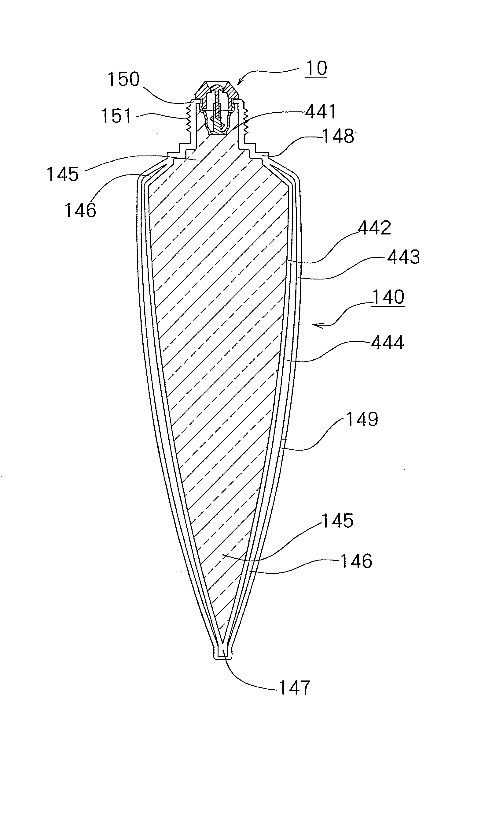
[0198] This tube-type container possesses a container main unit 140, a lid material 110 which is placed at the top of the container main unit 140, and a valve mechanism 10.

[0199] The container main unit 140 possesses a discharge port 441 for discharging a fluid, which is formed at one end of the container main unit, a flange portion 150 (See FIG. 35 and FIG. 36) formed in the vicin...


PUM


Abstract

A valve mechanism adapted for a fluid-discharging port of a tube-type fluid container includes: a valve seat portion having a valve seat surface with an opening for passing a fluid therethrough; a valve portion comprising a valve body having a shape corresponding to the valve seat surface with the opening, and a shaft connected to the valve body and extending downward from the valve body, and a valve support portion for elastically urging the valve body downward to close the opening. An annular convex portion is further formed between the valve seat surface and the valve body on the valve seat surface or the valve body for closing the opening with the valve body at the annular convex portion.

Description

CROSS REFERENCE TO RELATED APPLICATIONS [0001] This is a divisional application of U.S. patent application Ser. No. 10 / 619,205, filed Jul. 14, 2003, the disclosure of which is herein incorporated by reference in its entirety.BACKGROUND OF THE INVENTION [0002] 1. Field of the Invention [0003] The present invention relates to a valve mechanism, particularly to a valve mechanism which can be used for a tube-type fluid container. Further, the present invention relates to a tube-type fluid container storing a fluid inside it. [0004] 2. Description of the Related Art [0005] A valve mechanism as described in Japanese Patent Laid-open No. 2001-179139 has a spherical valve body and a spring for giving momentum to the valve body toward a valve seat has been used. Manufacturing costs of the valve mechanism using the spherical valve body and the spring, however, tend to be high. [0006] A valve mechanism having a resinous valve seat, and a resinous valve body which moves between a closed positio...

Claims


Application Information

Patent Timeline
Patent Type & Authority Applications(United States)
IPC IPC(8): B65D25/40B65D35/56B65D37/00B65D35/14B65D35/46B65D47/20
CPCB65D35/14B65D47/2075B65D35/46B65D47/20
Inventor MASUDA, MASATOSHI
Owner MASUDA MASATOSHI
Why Eureka
Try Eureka