Bottle cap
- Summary
- Abstract
- Description
- Claims
- Application Information
AI Technical Summary
Benefits of technology
Problems solved by technology
Method used
Image
Examples
Embodiment Construction
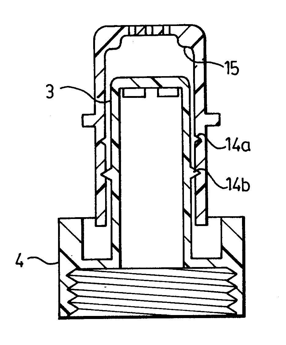
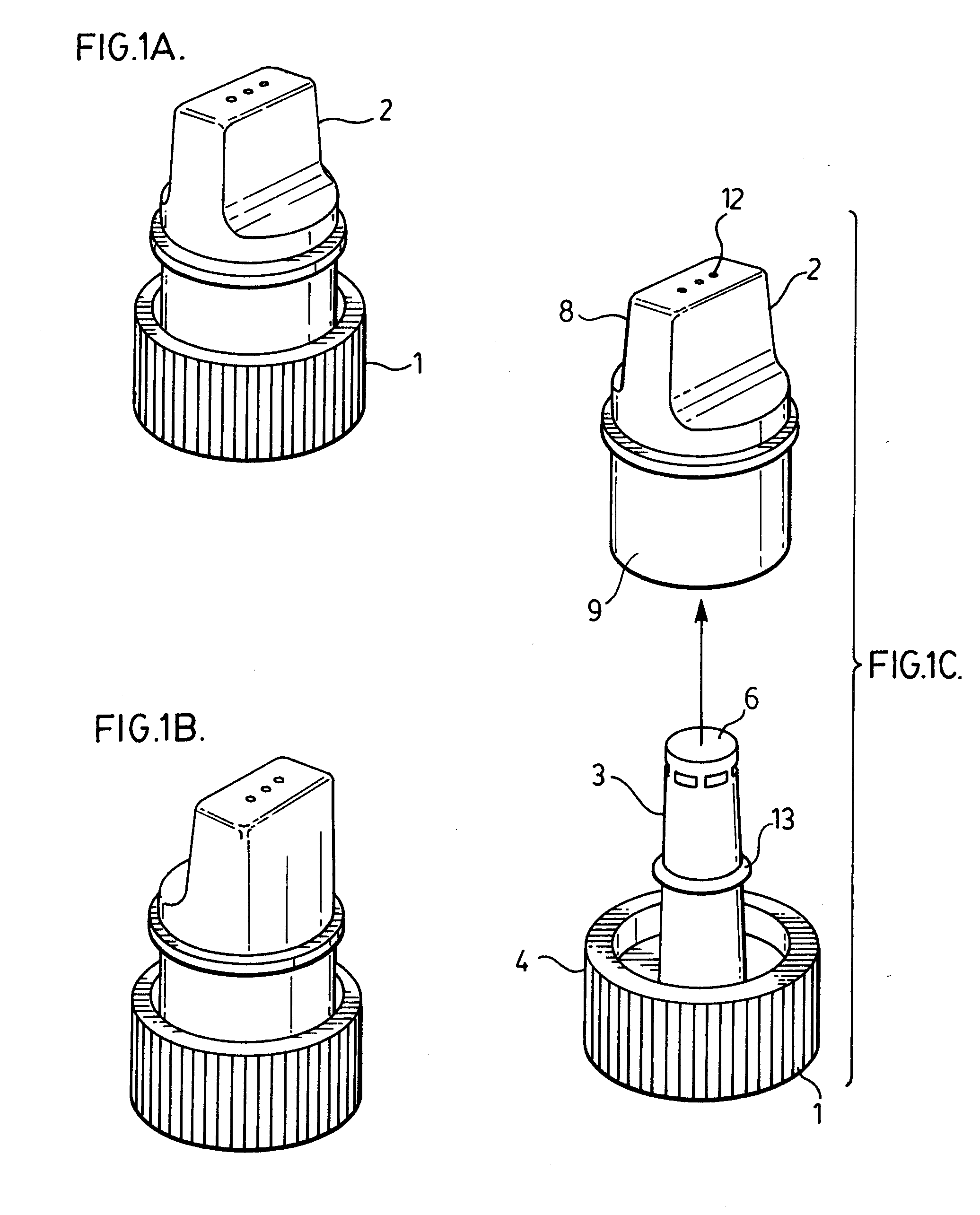
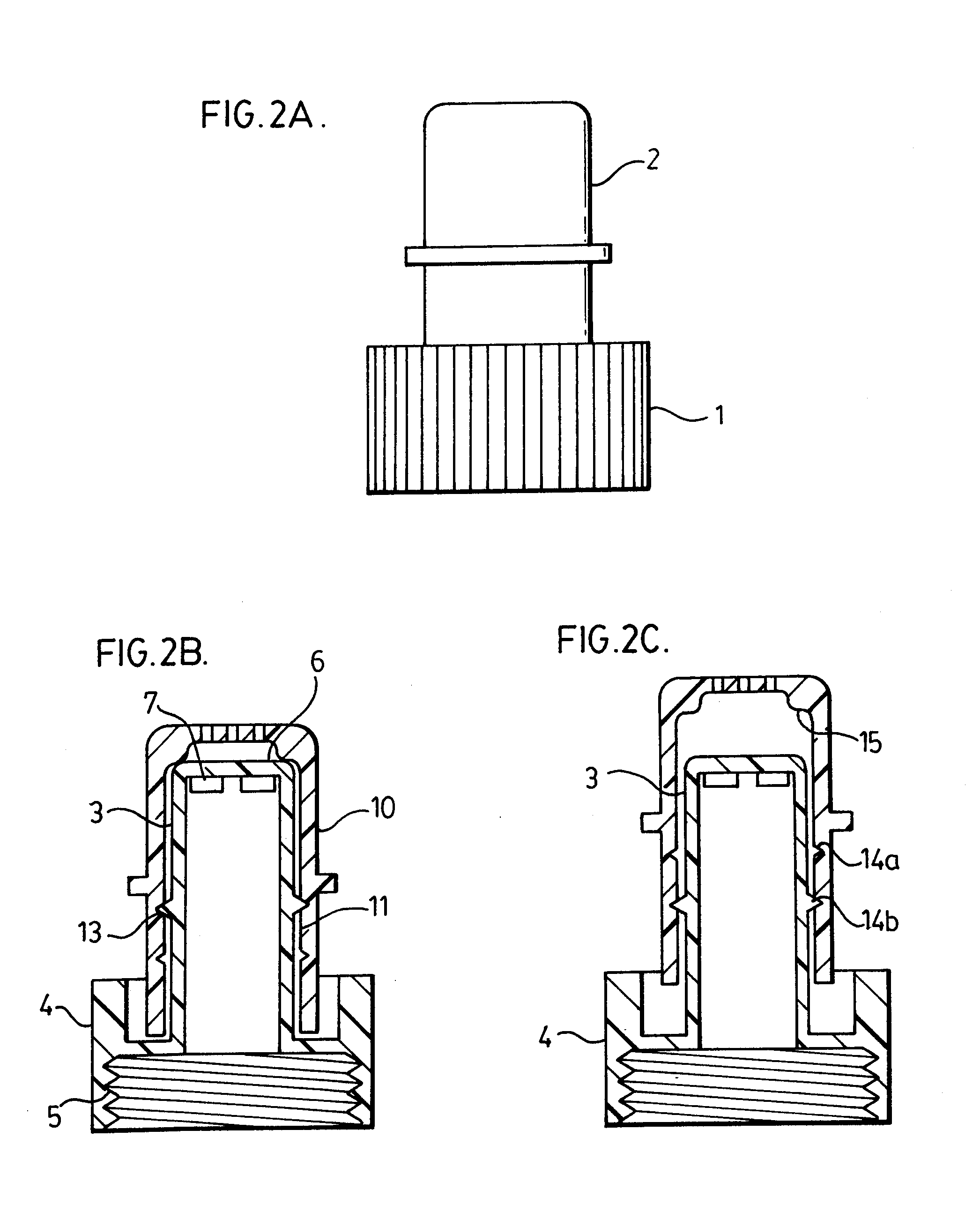
[0031]The spout-cap of the present invention is shown in FIGS. 1A to 1C and comprises a central body 1 and an end-cap 2. FIGS. 1A and 1B provide perspective views of the assembled spout-cap of the present invention and FIG. 1C shows the individual components of the spout-cap. FIGS. 2A and 3A provide further views of the assembled spout-cap of FIG. 1A. The central body 1 preferably comprises a threaded portion 3 and a neck portion 4, shown in FIG. 1C. The threaded portion 4, having an inside surface that is threaded 5, is adapted to be sealably affix the spout-cap onto a common beverage bottle having a threaded bottle neck, for example plastic beverage bottles such as those used for bottled water, soft-drinks and juices by engaging the threads of the bottle neck. The neck portion 3 extends from the threaded portion 4 and ends in a fluid-impermeable apex 6, serving as a stopper. The neck portion 3 is further perforated, preferably near the apex (without perforating the apex 6 itself) ...
PUM
 Abstract
Description
Claims
Application Information
 - R&D
- Intellectual Property
- Life Sciences
- Materials
- Tech Scout
- Unparalleled Data Quality
- Higher Quality Content
- 60% Fewer Hallucinations
Browse by: Latest US Patents, China's latest patents, Technical Efficacy Thesaurus, Application Domain, Technology Topic, Popular Technical Reports.
© 2025 PatSnap. All rights reserved.Legal|Privacy policy|Modern Slavery Act Transparency Statement|Sitemap|About US| Contact US: help@patsnap.com


