
Electronic Shift Lever Assembly

a technology of shift lever and assembly, which is applied in the direction of instruments, galvano-magnetic hall-effect devices, transportation and packaging, etc., can solve the problems of high manufacturing cost, inability to effectively apply linear hall sensors or switch hall sensors, and inability to accurately select driving modes

Active Publication Date: 2008-02-21
SL CORP
View PDF6 Cites 62 Cited by
  • Summary
  • Abstract
  • Description
  • Claims
  • Application Information

AI Technical Summary

Problems solved by technology

However, it is difficult to effectively apply the linear hall sensor or the switch hall sensor when the shift lever moves not only in linear path but also in complicated paths.
Consequently, the structures of the conventional systems become complicated, causing high manufacturing costs.
Moreover, since the conventional automatic gear transmissions, which drive manual valve using cable tension as the position of the shift lever is adjusted by a driver, driving mode can be incorrectly selected when the driver makes a mistake while driving or is inexperienced in manipulating the shift lever.
Furthermore, the driver may not able to select a desired mode due to aging of the cable, and fuel efficiency may decrease by heavy weight of vehicle parts.
Also, the conventional automatic gear transmissions, generally, have a large size so as to cause the utilization of vehicle space to be limited.

Method used


Image

  • Electronic Shift Lever Assembly
  • Electronic Shift Lever Assembly
  • Electronic Shift Lever Assembly

Examples


Embodiment Construction

[0043]The present invention will now be described more fully with reference to the accompanying drawings, in which exemplary embodiments of the invention are shown. The invention may, however, be embodied in many different forms and should not be construed as being limited to the embodiments set forth herein. Rather, these embodiments are provided so that this disclosure will be thorough and complete, and will fully convey the concept of the invention to those skilled in the art. Like reference numerals in the drawings denote like elements, and thus their description will be omitted.

[0044]Hereinafter, exemplary embodiments of the present invention will be described in detail with reference to the accompanying drawings.

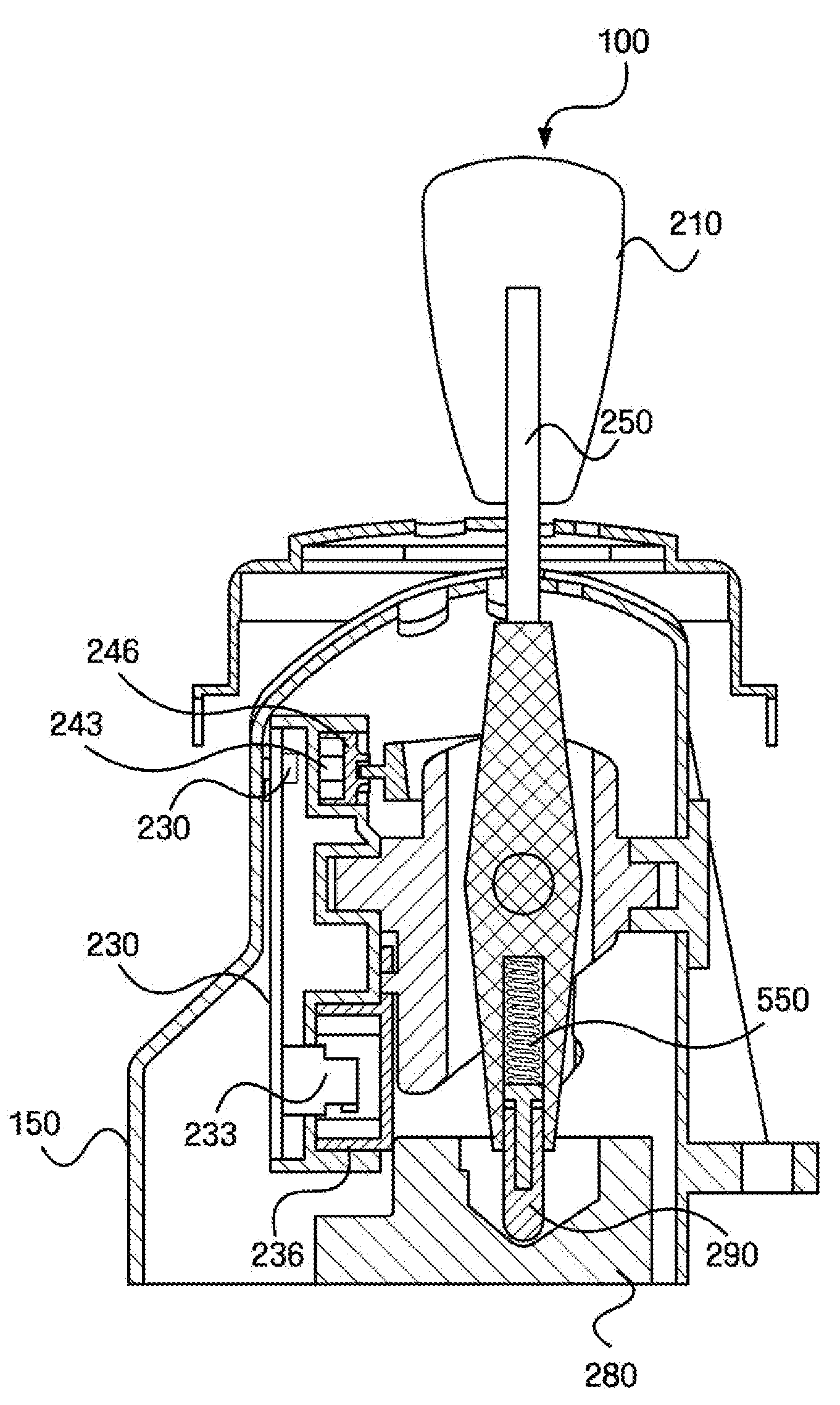
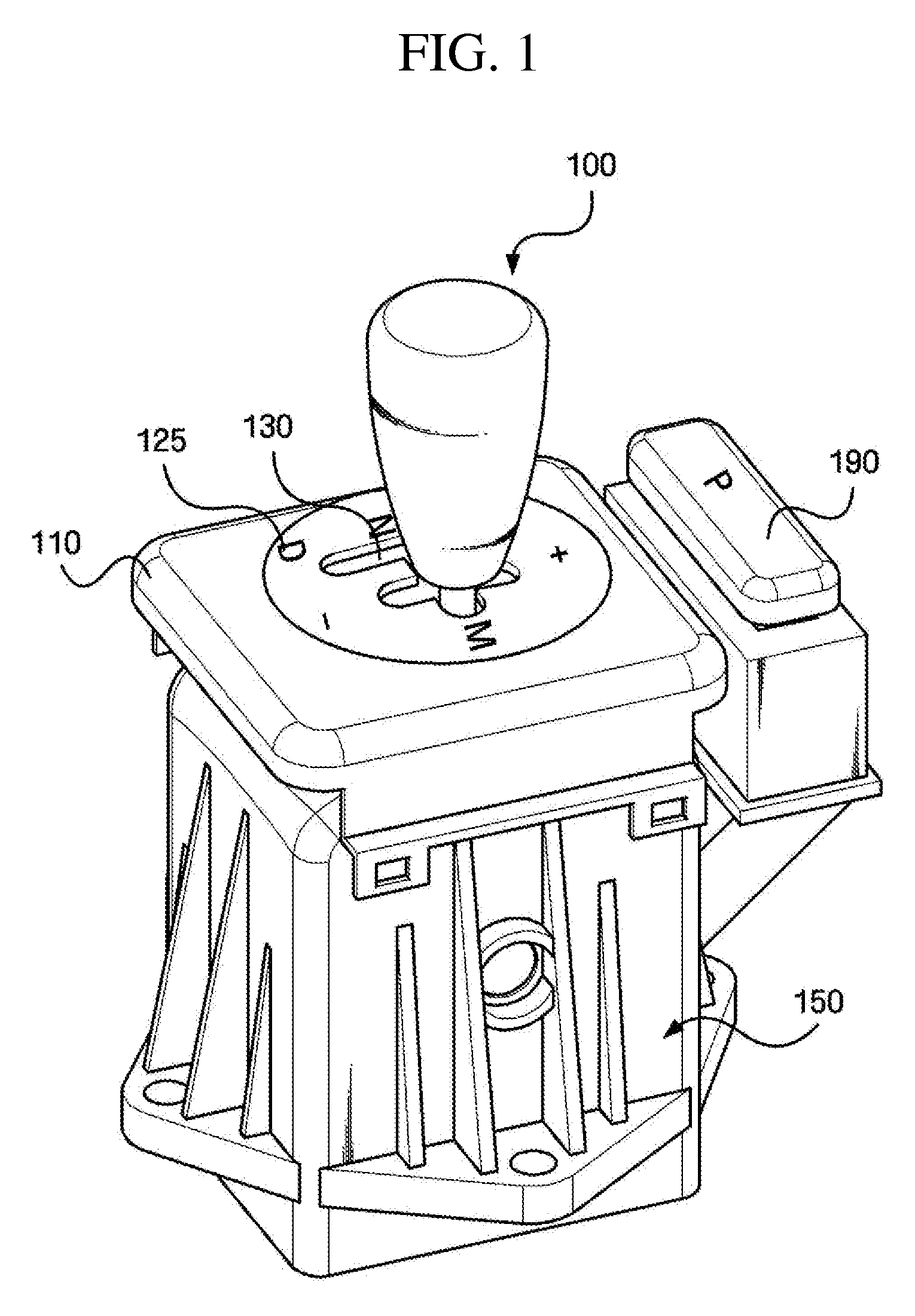
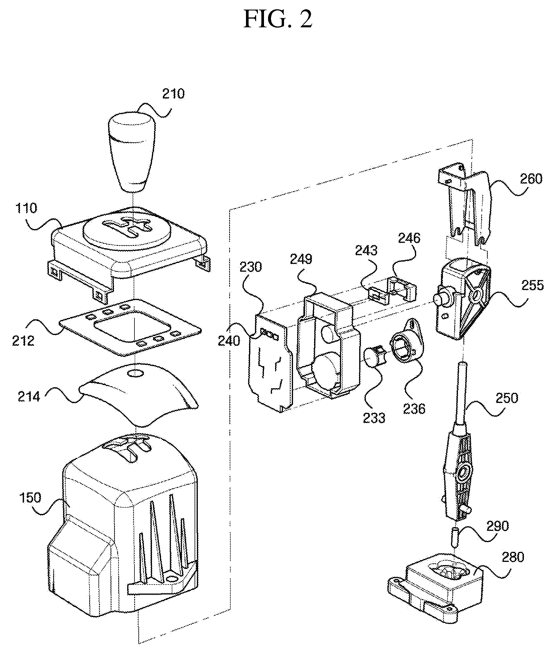
[0045]FIG. 1 is a perspective view of an electronic shift lever assembly using hall sensors according to an exemplary embodiment of the present invention. FIG. 2 is an assembly view of the electronic shift lever assembly of FIG. 1.

[0046]Referring to FIG. 1, the electro...


PUM


Abstract

Provided is an electronic shift lever assembly which can select a gear position by sensing the movement of a shift lever in forward, backward, right and left directions. The electronic shift lever assembly includes: a shift lever movable to select a gear position; a first sensor unit comprising a plurality of linear hall sensors for sensing vertical movement of the shift lever; and a second sensor unit comprising a plurality of switch hall sensors for sensing horizontal movement of the shift lever.

Description

CROSS-REFERENCE TO RELATED APPLICATION[0001]This application claims priority from Korean Patent Application No. 10-2006-0077863 filed on Aug. 17, 2006, the disclosure of which is incorporated herein by reference in its entirety.BACKGROUND OF THE INVENTION[0002]1. Technical Field[0003]The present invention relates to an electronic shift lever assembly, and more particularly, to an electronic shift lever assembly which can select a gear position by sensing the movement of a shift lever in forward, backward, right and left directions using hall sensors.[0004]2. Background Art[0005]A vehicle transmission changes gear ratio according to vehicle speed so that engine can rotate at a constant speed. The gear ratio can be changed by manipulation of the shift lever of the transmission. The transmission is generally classified into a manual transmission in which gear position is manually changed by a driver and an automatic transmission in which gear position is changed automatically according...

Claims


Application Information

Patent Timeline
Patent Type & Authority Applications(United States)
IPC IPC(8): G01B7/30G01B7/14
CPCF16H59/0204Y10T74/2003G01D5/145F16H59/105B60K20/02B60W2420/503
Inventor HEO, CHUN-NYUNGJUNG, YONG-EONSONG, HEA-SEOK
Owner SL CORP
Learn More