Liquid crystal display device

a display device and liquid crystal technology, applied in static indicating devices, lighting and heating apparatus, instruments, etc., can solve the problems of easy breakage of liquid crystal panels, difficulty in accurately positioning leds and light guide plates, etc., to enhance the utilization efficiency of light, reduce the thickness of light radiation surfaces of light guide plates, and enhance the effect of external force strength

Active Publication Date: 2008-02-21
PANASONIC LIQUID CRYSTAL DISPLAY CO LTD
View PDF5 Cites 89 Cited by
  • Summary
  • Abstract
  • Description
  • Claims
  • Application Information

AI Technical Summary

Benefits of technology

[0010]The present invention has been made in view of the above-mentioned drawbacks and it is an object of the present invention to provide a liquid crystal display device which can enhance the utilization efficiency of light, can reduce irregularities of radiation light, and can enhance the positioning accuracy of LEDs.
[0014]By alleviating a force attributed to the inclination surface which is applied to the liquid crystal panel using the optical sheet, a strength for an external force is enhanced and, at the same time, by arranging a reflective member on the inclination surface, light which is leaked from the inclination surface is reflected and the leaked light is returned to the light-guide-plate side from the inclination surface and hence, it is possible to enhance the utilization efficiency of light.
[0015]By forming the projecting portion on a light incidence surface of the light guide plate, a light guide plate is arranged between the LEDs and hence, the light which is radiated in the side surface direction of the LED is made to be incident on the light guide plate thus increasing the light which is incident from between the LEDs whereby it is possible to reduce irregularities of light radiated from the light guide plate.
[0016]Further, by forming the inclination surface on the light guide plate, a thickness of the light radiation surface of the light guide plate may be set to a value equal to or less than a thickness of the LEDs thus realizing the reduction of thickness and, at the same time, it is possible to overcome a drawback which arises due to the provision of the inclination surface, that is, a drawback that it is difficult to adhere the printed circuit board which mounts the LEDs thereon to the light guide plate. That is, by allowing the printed circuit board to be adhered to the light guide plate in a state that the projecting portion is formed between the LEDs, it is possible to enhance positioning accuracy of the LEDs.
[0017]Further, by arranging the optical sheet on the inclination surface of the light guide plate, a gap which is generated attributed to the inclination surface is filled with the optical sheet thus preventing a rupture of the liquid crystal panel attributed to the external force.
[0018]Further, the reflective member is arranged on the inclination surface and hence, the light which is leaked from the inclination surface is returned to the light-guide-plate side thus enhancing the utilization efficiency of light.

Problems solved by technology

Accordingly, it has been difficult to accurately perform positioning of the LEDs and the light guide plate.
Along with the reduction of a thickness of the equipment, there also arises a drawback that a liquid crystal panel is easily broken due to an external force.

Method used


Image

  • Liquid crystal display device
  • Liquid crystal display device
  • Liquid crystal display device

Examples


Embodiment Construction

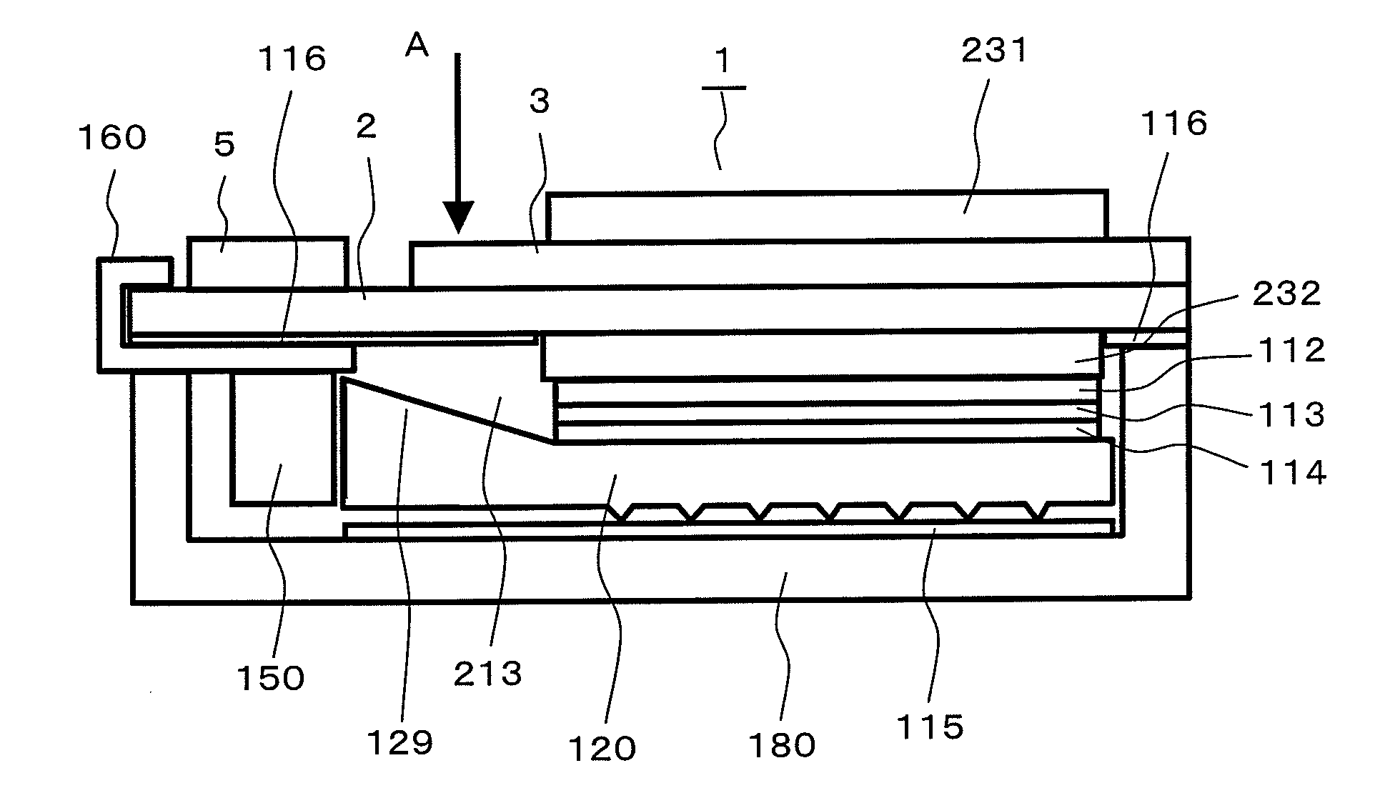
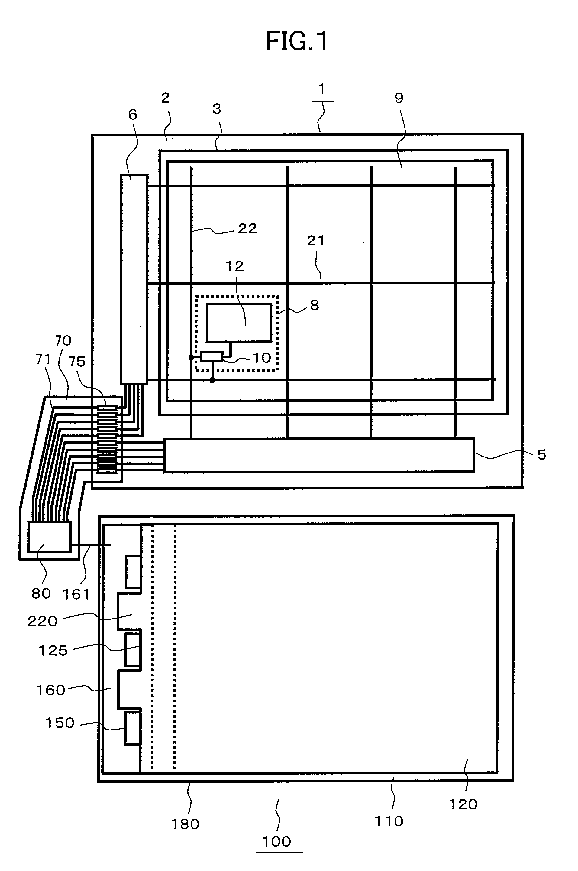
[0037]FIG. 1 is a plan view showing a liquid crystal display device 100 according to the present invention. The liquid crystal display device 100 is constituted of a liquid crystal panel 1, a backlight 110 and a control circuit 80. Signals and power source voltages necessary for a display by the liquid crystal display device 100 are supplied from the control circuit 80. The control circuit 80 is mounted on a flexible printed circuit board 70, and signals are transmitted to the liquid crystal panel 1 via lines 71 and terminals 75.

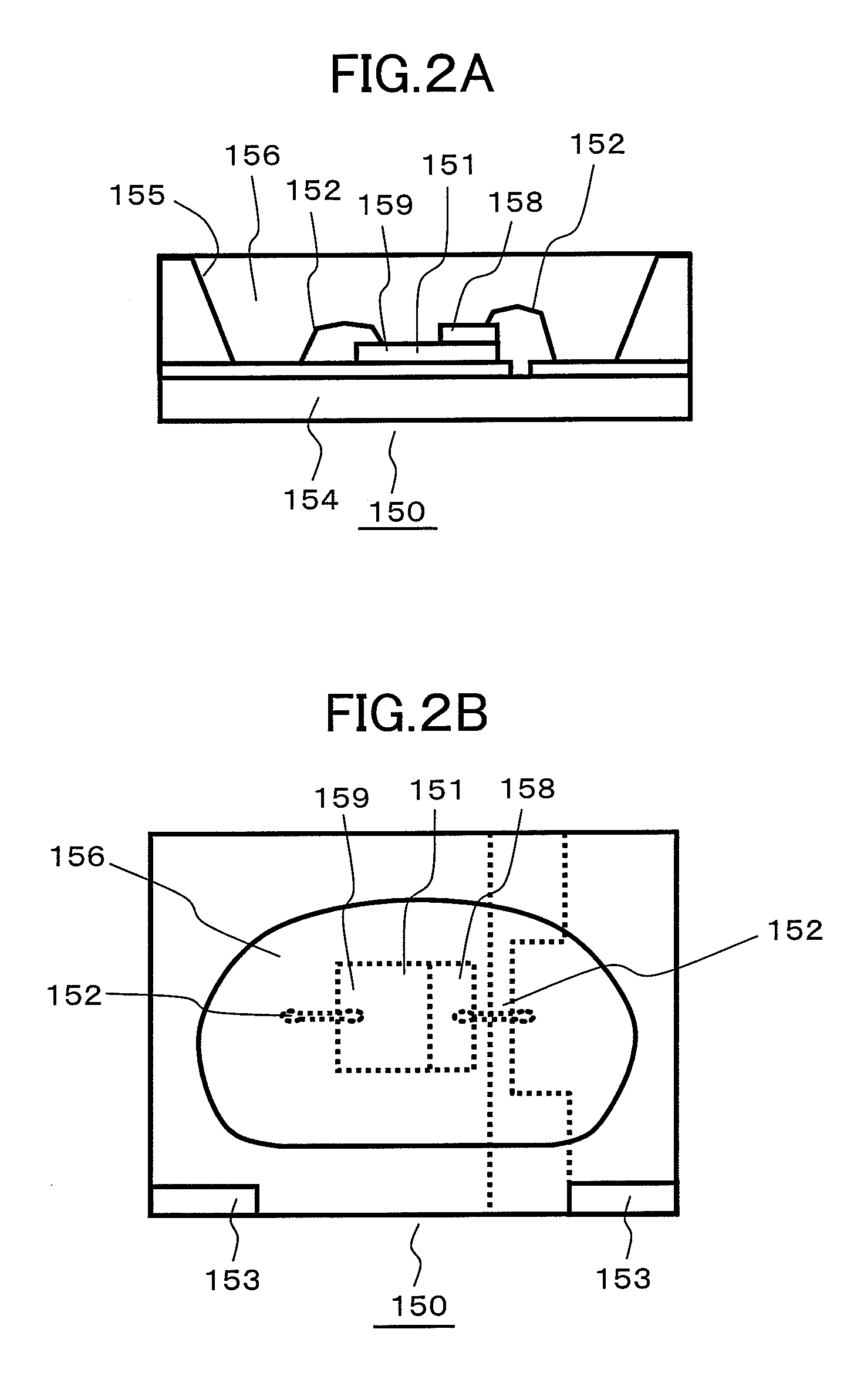
[0038]The backlight 110 is constituted of a light guide plate 120, LEDs 150 and a housing case 180. The backlight 110 is provided for radiating light to the liquid crystal panel 1. The liquid crystal panel 1 performs a display by controlling a transmission quantity or a reflection quantity of light radiated from the backlight 110. Here, the backlight 110 is mounted on a back surface side or a front surface side of the liquid crystal panel 1 in a stacked mann...


PUM

PropertyMeasurementUnit
thicknessaaaaaaaaaa
angleaaaaaaaaaa
total thicknessaaaaaaaaaa

Abstract

The present invention provides a backlight of a liquid crystal display device having an inclination surface on a light guide plate and preventing a breakage of a liquid crystal panel, wherein light which leaks from the inclination surface is made to return to the light guide plate and the adhesiveness of the light guide plate and a flexible printed circuit board is increased. In a liquid crystal display device having a backlight which radiates light to a liquid crystal panel, LEDs are formed on a light guide plate formed on the backlight as light emitting elements. Between the plurality of light emitting elements, a projecting portion of the light guide plate is formed, and a reflection member is formed on an adhesive sheet which adheres a projection member and a flexible printed circuit board to each other. By arranging the reflective member and the cushion member close to an inclination surface, light from the inclination surface is made to return to a light guide plate side, and an external force from the outside can be alleviated by a cushion member.

Description

BACKGROUND OF THE INVENTION[0001]1. Field of the Invention[0002]The present invention relates to a light source of a non-self-luminous display device, and more particularly to a liquid crystal display device having a backlight which includes a light guide plate and uses an LED as a light source.[0003]2. Background Art[0004]Recently, the liquid crystal display device has been popularly used as a display device. Particularly, the liquid crystal display device is used as a display part of portable equipment because of a reduced thickness, a reduced weight and small electric power consumption.[0005]However, the liquid crystal display device is not self-luminous and hence, the display device requires an illumination means. In general, as a lighting device which is used for the liquid crystal display device, a flat lighting device referred to as a backlight is popularly used. Conventionally, although a cold cathode fluorescence light tube has been used as a light emitting element (also re...

Claims


Application Information

Patent Timeline
Patent Type & Authority Applications(United States)
IPC IPC(8): G02F1/13357
CPCG02B6/0021G02B6/0038G02B6/0046G02B6/0068G02F2001/133314G02B6/0083G02B6/0091G02F1/133615G02B6/0073G02F1/133314
Inventor TAKAHASHI, YOSHIAKINAKAMOTO, HIROSHIHANADA, HIDEHIRO
Owner PANASONIC LIQUID CRYSTAL DISPLAY CO LTD
Why Eureka
Try Eureka