
Apparatus, method, system and software product for a scheduling synchronization mechanism in a multi-hop environment

a multi-hop environment and scheduling synchronization technology, applied in the field of telecoms, can solve the problems of wasting bandwidth grants, bwa has limited reach so far, and the issue of scheduling synchronization is raised

Inactive Publication Date: 2008-02-21
NOKIA CORP
View PDF6 Cites 10 Cited by
  • Summary
  • Abstract
  • Description
  • Claims
  • Application Information

AI Technical Summary

Benefits of technology

[0021] In order to synchronize bandwidth grants and / or polls for uplink traffic over multiple hops, the uplink time interval pertaining to the information in each resource allocation frame should vary for each relay station (RS) on the path, and should be specified in the resource allocation frame (e.g. the UL-MAP). An advantage of the present invention is that no delay is generated due to scheduling non-synchronization between multiple hops on the path. No waste of bandwidth or potential packet drop is introduced. Another advantage is that the invention can be used to introduce relays in a network without modification to legacy end terminals.
is that no delay is generated due to scheduling non-synchronization between multiple hops on the path. No waste of bandwidth or potential packet drop is introduced. Another advantage is that the invention can be used to introduce relays in a network without modification to legacy end terminals.

Problems solved by technology

BWA has had limited reach so far, in part because of the unmet need for a universal standard.
However, when the multi-hop concept is introduced in a wireless environment, issues related to scheduling synchronization are raised.
However, the scheme in Application 60 / 777,655 leads to waste of bandwidth grants in the first couple of frames in order to synchronize among multiple hops.
Furthermore, if the buffering time in the intermediate nodes are too long, the user traffic may need to be dropped since the end-to-end delay already exceeds the limit.

Method used


Image

  • Apparatus, method, system and software product for a scheduling synchronization mechanism in a multi-hop environment
  • Apparatus, method, system and software product for a scheduling synchronization mechanism in a multi-hop environment
  • Apparatus, method, system and software product for a scheduling synchronization mechanism in a multi-hop environment

Examples


Embodiment Construction

[0029] An embodiment of the present invention will now be detailed with the aid of the accompanying figures, building upon the existing technology. It is to be understood that this embodiment is merely an illustration of one particular implementation of the invention, without in any way foreclosing other embodiments and implementations.

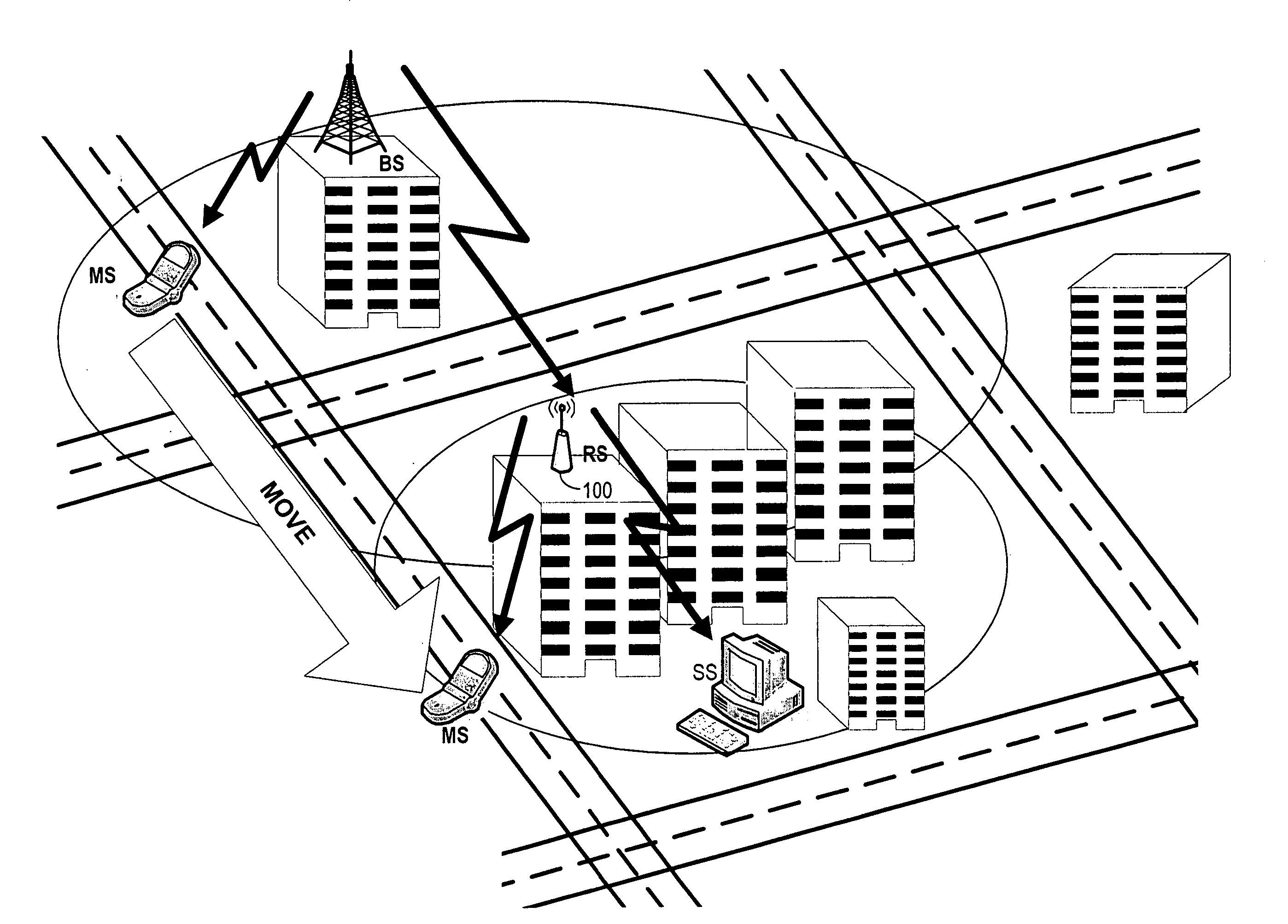
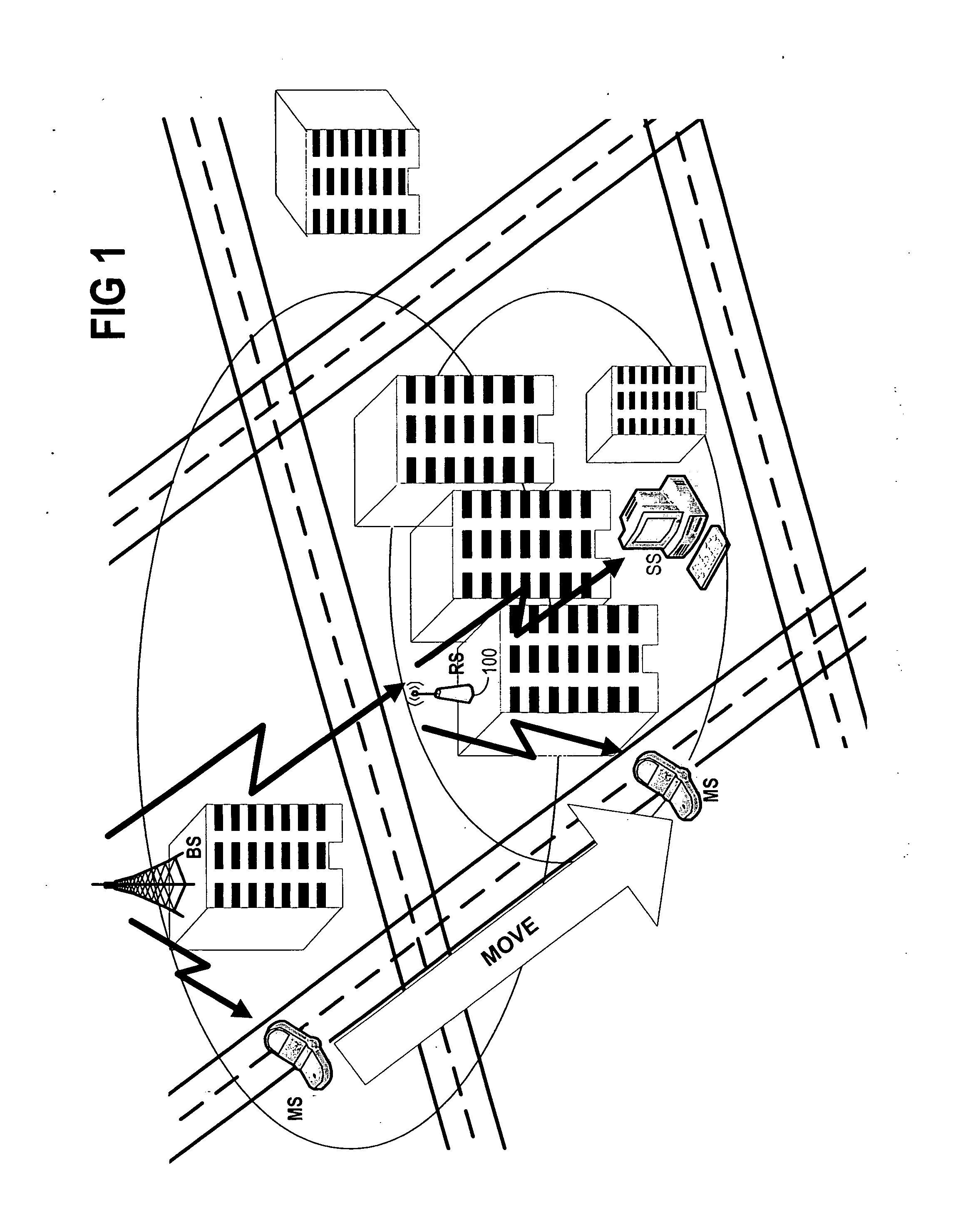
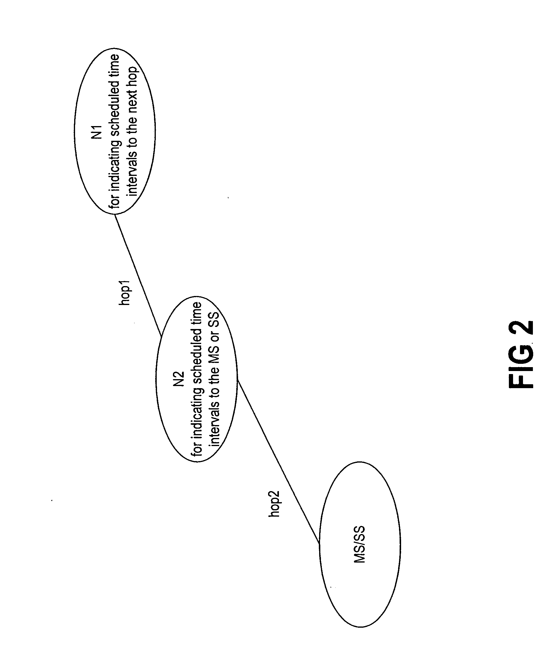
[0030] An exemplary usage scenario of a Relay Station 100 is shown in FIG. 1, for indicating scheduled time intervals to neighbors that are directly downlink. A simple multi-hop environment is illustrated in FIG. 2. MS / SS, Node 1 (N1) and Node 2 (N2) are connected to each other using wireless technology such as WiMax or WLAN. MS / SS acts as the source / destination of the user traffic. In the mesh case, N2 is the intermediate node on the path between the source and destination, while N1 could be the intermediate node or the correspondent node for the MS / SS (i.e., the source / destination of the user traffic). In the relay case, N2 is one RS on the path be...


PUM


Abstract

A method is disclosed for commencing distributed scheduling of uplink communication, in a component of a multihop relay system of a wireless network. The component sends information that is related to the scheduling, to a direct downlink neighbor along a multihop path. This information at least indicates a time interval available for the uplink communication, that time interval corresponding to a hop of the path between the neighbor and the component. The time interval is shorter for a hop that is downstream from another hop which corresponds to a longer time interval.

Description

CROSS REFERENCE TO RELATED APPLICATION [0001] Priority is claimed to U.S. Provisional Application No. 60 / 835,786 filed Aug. 4, 2006.BACKGROUND OF THE INVENTION [0002] 1. Technical Field [0003] The present invention pertains to the field of telecommunications. More particularly, the present invention pertains to scheduling for data transmission. [0004] 2. Discussion of Related Art [0005] Broadband wireless access (BWA) has become an attractive way to meet escalating business demand for rapid Internet connection and integrated data, voice and video services. One of the most compelling aspects of BWA technology is that networks can be created in just weeks by deploying a small number of base stations on buildings or poles to create high-capacity wireless access systems. BWA has had limited reach so far, in part because of the unmet need for a universal standard. While providing such a standard is important for developed countries, it is even more important for the developing world wher...

Claims


Application Information

Patent Timeline
Patent Type & Authority Applications(United States)
IPC IPC(8): H04L12/28H04L69/28
CPCH04B7/2606H04W40/22H04W72/1268H04L69/28H04W84/047H04W84/18H04W72/1289H04W72/23
Inventor ZHENG, HAIHONG
Owner NOKIA CORP
Learn More