
Liquid Chromatograph

a liquid chromatograph and chromatograph technology, applied in the field of liquid chromatographs, can solve the problems of difficult to reliably identify the same components in each, and difficult to determine which components are the target components for concentration, and achieve the effect of reliable identification

Inactive Publication Date: 2008-02-21
SUMITOMO CHEM CO LTD
View PDF6 Cites 16 Cited by
  • Summary
  • Abstract
  • Description
  • Claims
  • Application Information

AI Technical Summary

Benefits of technology

[0011] A liquid chromatograph of this invention employs, as first and second detection devices, photodiode array detectors, infrared detectors, radioisotope detectors, or fluorescence detectors, and so it is possible to simply and reliably judge that a target component detected by the first detection device and a component detected by the second detection device are the same, without any influence from background components, contaminant components, components remaining in the fractionation flow path, or similar.

Problems solved by technology

However, when the types of the first analysis column and the second analysis column as well as the compositions of the mobile phases therein are different, the holding times of the component detected by the first UV detector and the component detected by the second UV detector are different, and so it has been difficult to reliably identify the component as being the same in each.
Further, because of the high sensitivity, for example background components, contaminant components, components remaining in the fractionation flow path, and other components not intended for concentration may also be detected by the second UV detector, and it has been difficult to determine which component is the target component for concentration.

Method used


Image

  • Liquid Chromatograph
  • Liquid Chromatograph
  • Liquid Chromatograph

Examples


Embodiment Construction

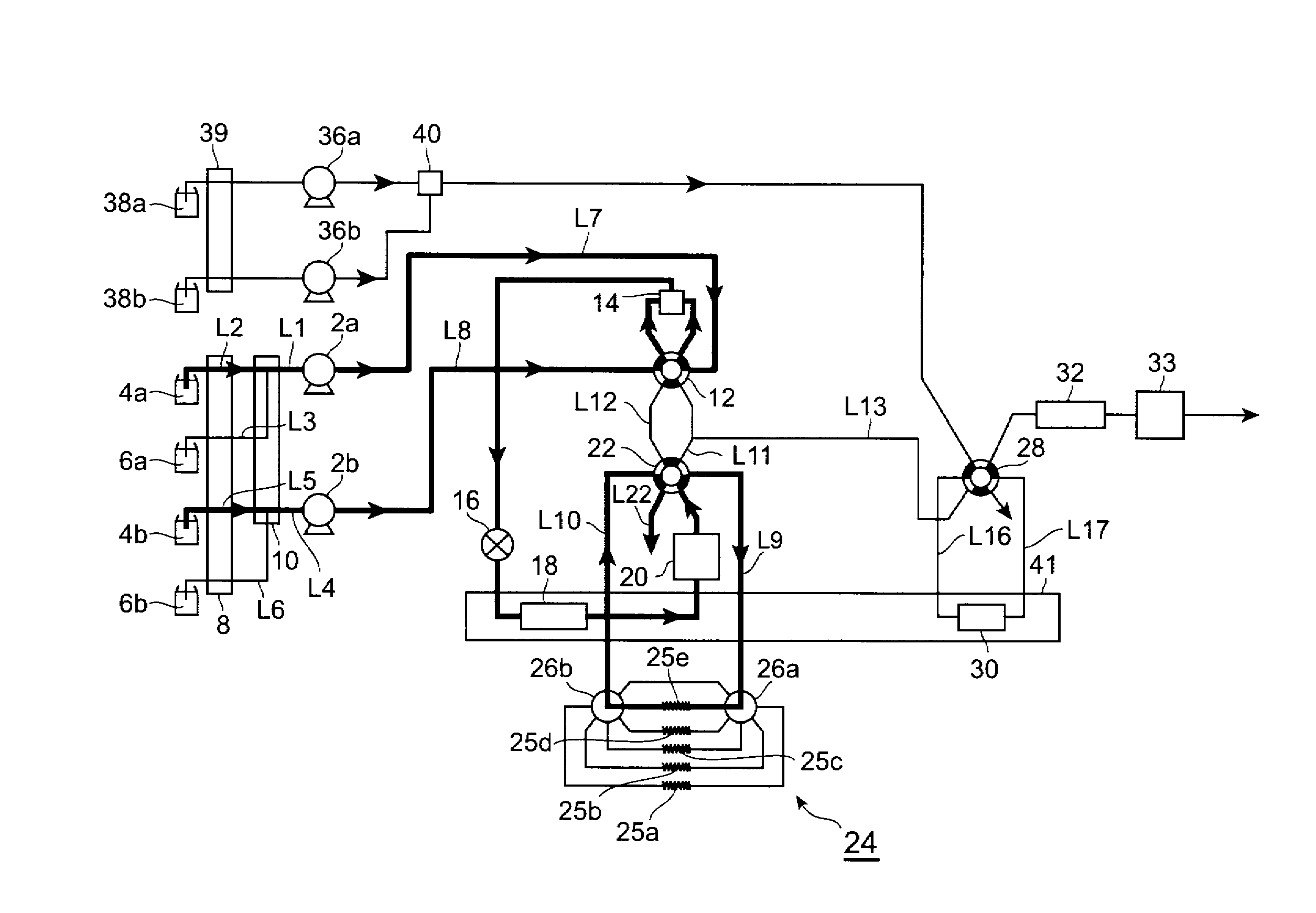
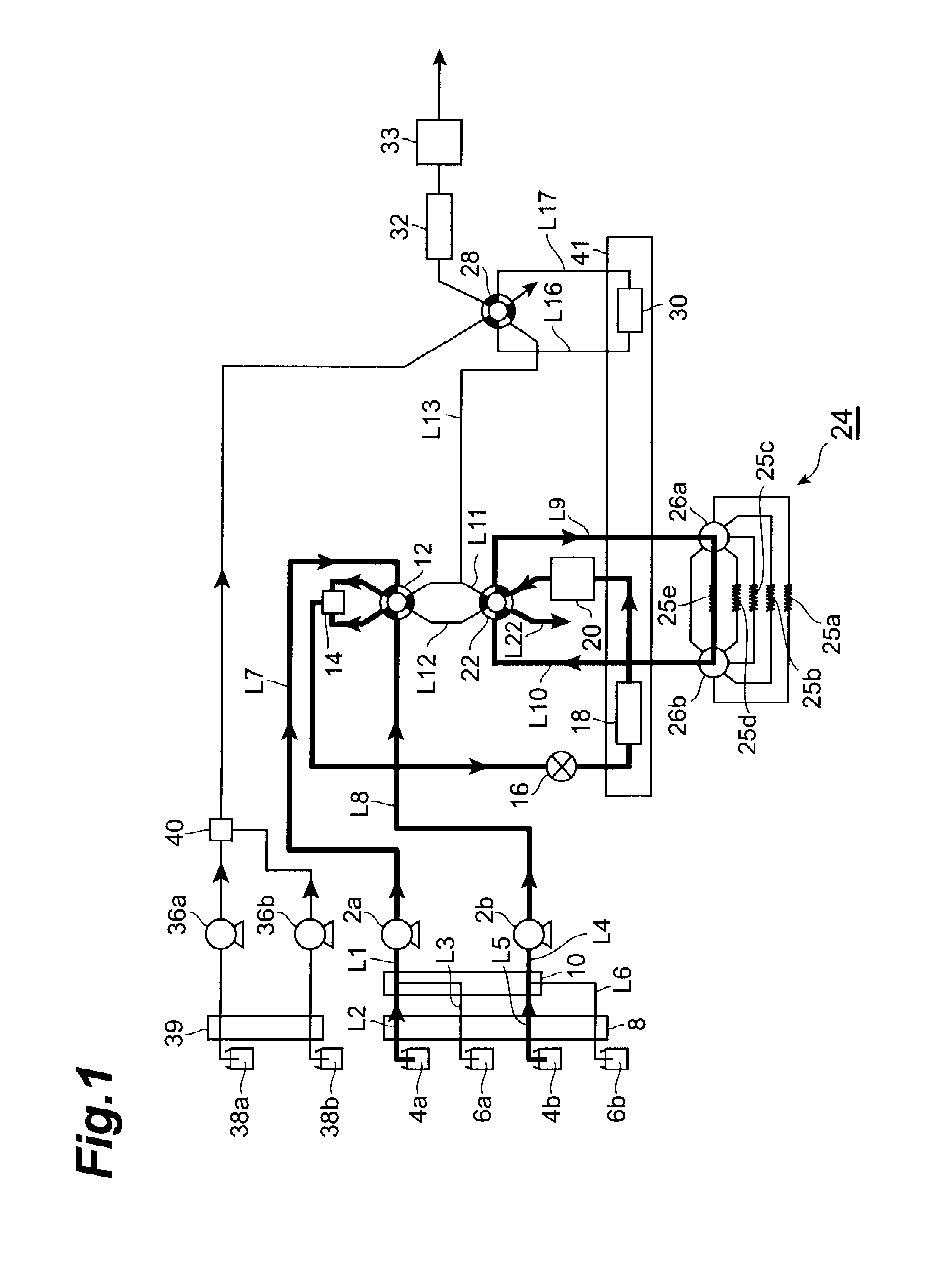
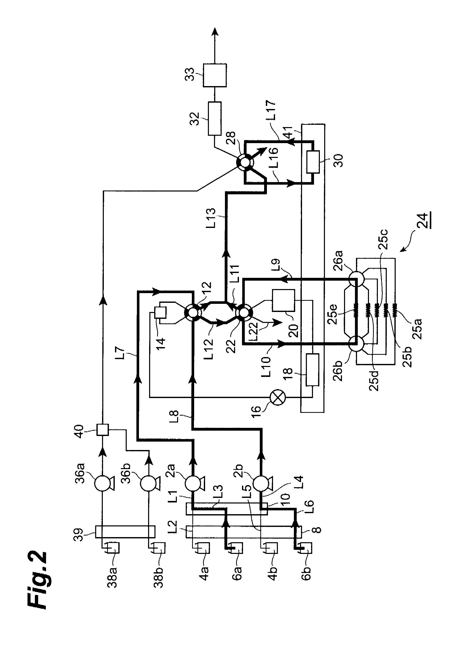
[0046] Below, the invention is explained in detail, referring to the drawings. FIG. 1 shows one aspect of a liquid chromatograph of the invention. The liquid chromatograph shown in FIG. 1 is a liquid chromatograph using, as first and second detection devices, photodiode array detectors (hereafter abbreviated to “PDA detectors”), and comprising one trap column.

[0047] The liquid pumps 2a and 2b may be any pumps capable of sending a solvent, such as an organic solvent, water, or similar, which can be used as a mobile phase. It is preferable that it be possible to set such pumps to arbitrary flow rates.

[0048] On the upstream side of the liquid pump 2a, a switching valve 10 is connected by a flow path L1, and the switching valve 10 and the organic solvent 4a comprised by the first mobile phase are connected by the flow path L2. Midway in the flow path L2 is provided an online degasser 8. The online degasser 8 has a function of preventing inclusion of air bubbles in the organic solvent ...


PUM

PropertyMeasurementUnit
wavelengthsaaaaaaaaaa
inner diameteraaaaaaaaaa

Abstract

A liquid chromatograph, comprising a first analysis column, which separates a component in a sample guided by a first mobile phase; first detection device for detection of the component; a fractionation flow path, which fractionates and holds in an isolation portion the component detected by the first detection device; a trap flow path, which sends the component held in the isolation portion into a trap column, and causes capture and concentration of the component in the trap column; a second analysis column, which separates the component which has been captured and concentrated in the trap column and is eluted from the trap column by a second mobile phase; and second detection device for detection of the component separated in the second analysis column, wherein the first and second detection devices have a detector selected from a group consisting of a photodiode array detector, an infrared detector, a radioisotope detector, and a fluorescence detector.

Description

TECHNICAL FIELD [0001] This invention relates to a liquid chromatograph. BACKGROUND ART [0002] Liquid chromatographs are known in which a component in a sample comprising a plurality of components is separated by a first analysis column, the component is detected by a first ultraviolet light detector (hereafter abbreviated “UV detector”), the component is captured and concentrated in a trap column, this is sent to a second analysis column and separated, and detection is performed by a second UV detector (see for example Patent References 1 and 2). [0003] In such a liquid chromatograph, UV detectors are used, and so an extremely large number of compounds having absorption in the ultraviolet region can be taken to be components for concentration; moreover, because detection sensitivity is high, even when the component for concentration is minute, a concentration operation can be performed, and in the second analysis column high-sensitivity analysis is possible. [0004] However, when th...

Claims


Application Information

Patent Timeline
Patent Type & Authority Applications(United States)
IPC IPC(8): G01N30/46G01N30/06G01N30/62G01N30/78G01N30/74G01N30/08
CPCG01N30/08G01N30/468G01N2030/085G01N30/78G01N2030/027G01N30/74G01N30/06G01N30/46G01N30/62
Inventor YAMASHITA, KAZUKOOKAMOTO, MASAHIKO
Owner SUMITOMO CHEM CO LTD
Learn More