Radio communications system and radio communications control method

a radio communications and control method technology, applied in the field of radio communications systems and radio communications control methods, can solve the problems of not being able to receive communications services from terminals outside the service area of omnidirectional antennas, unable to form beams in the direction of terminals, and unable to achieve efficient radio communications services. , to achieve the effect of reducing the number of hops and efficient radio communications services

Inactive Publication Date: 2008-02-21
FUJITSU LTD
View PDF11 Cites 33 Cited by
  • Summary
  • Abstract
  • Description
  • Claims
  • Application Information

AI Technical Summary

Benefits of technology

[0015]According to one aspect of the present invention, a terminal outside a regular service area covered by the omnidirectional antenna gain pattern of a radio base station notifies the radio base station of its existence through a radio relay station. Thereby, the radio base station promptly recognizes the network entry of the terminal, and switches to an adaptive array antenna gain pattern so as to direct a beam toward the direction of th

Problems solved by technology

This is because if the position of a terminal is not determined, it is not possible to form a beam in the direction of the terminal.
Accordingly, terminals outside the service area of the omnidirectional antenna cannot receive communications services.
As a result, in either the first or the second method, it takes a long time before network entry, and the amount of processing increases in both the radio base station and the terminal.
Further, neither the first nor the second method always ensures network entry, so that there also remains a problem in terms of service provision.
To help this, regarding only the downlink, power boosting for broadcast information is well known but this increases the interference to other cells (this means it is not effective for SINR improvement, although effective for SNR improvement) and the problem for the power amplifier unit from a linearity perspective.
However, this results in addition of the link between

Method used


Image

  • Radio communications system and radio communications control method
  • Radio communications system and radio communications control method
  • Radio communications system and radio communications control method

Examples


first embodiment

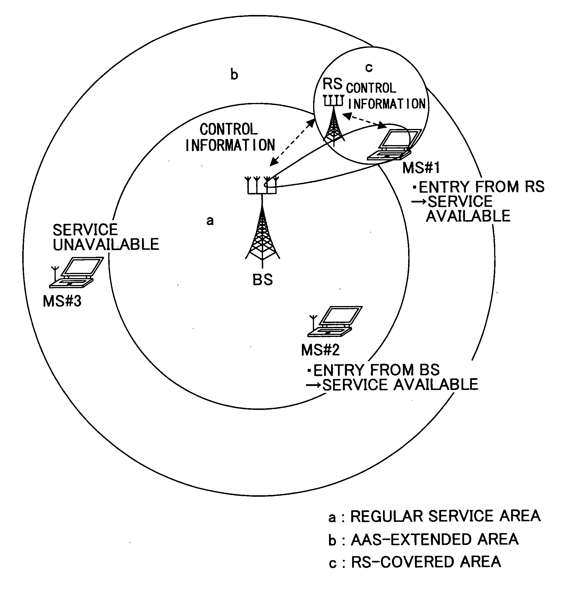
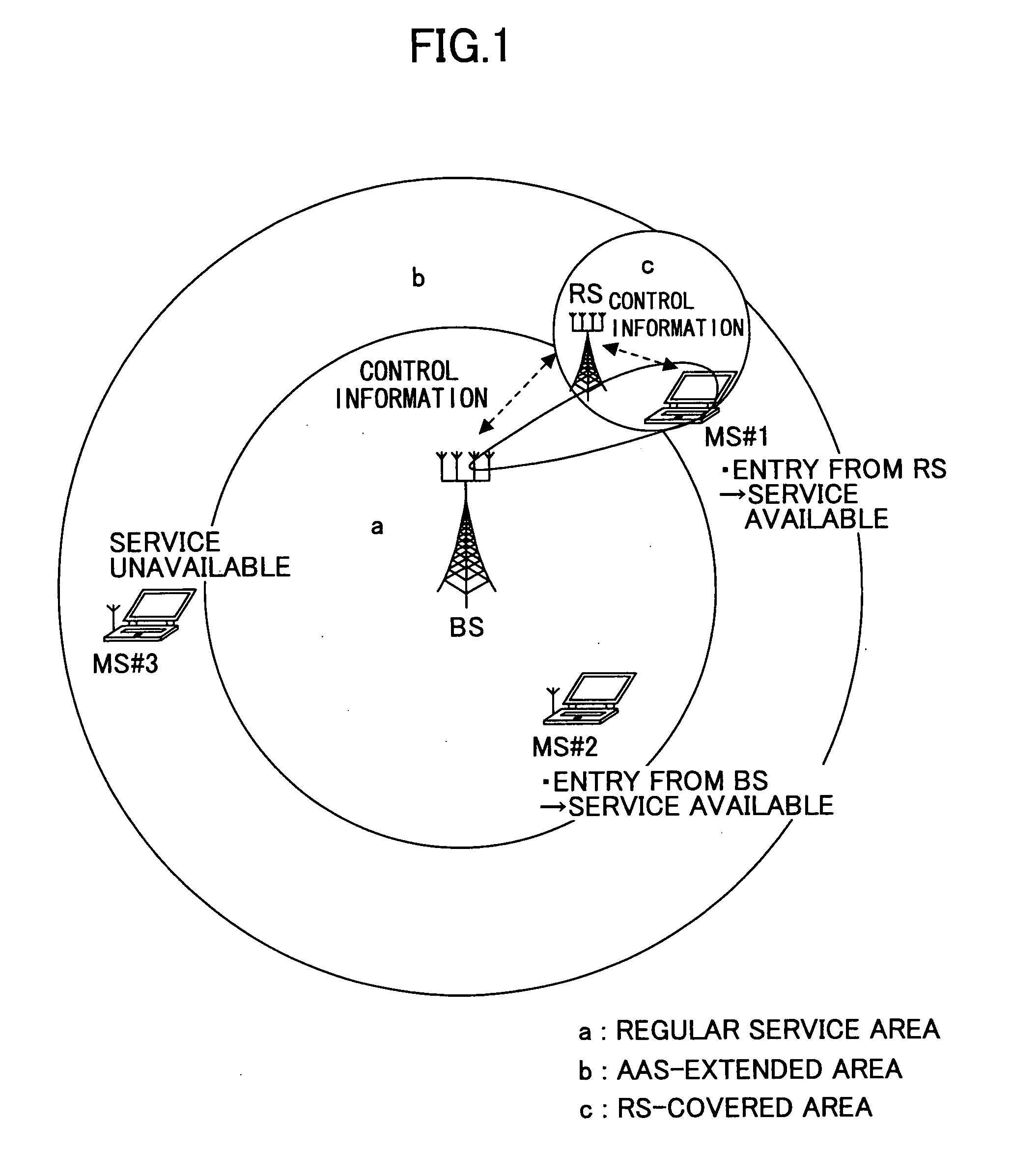
[0027]FIG. 1 is a diagram showing the relationship between the disposition of a radio base station (hereinafter also abbreviated as “BS”), terminals or mobile stations (hereinafter also abbreviated as “MS#1, MS#2, and MS#3), and a radio relay station (hereinafter also abbreviated as “RS”) and service areas according to a first embodiment of the present invention. As examples of service areas, FIG. 1 shows a regular service area a, which is a service area in the case where the BS performs no beamforming or forms no beam; an AAS-extended area b, which is an extended service area in the case where beamforming by an adaptive array system (AAS) or a system according to a directional antenna gain pattern is performed; and an RS-covered area c, which is a service area covered by the RS. Further, as examples of terminals, FIG. 1 shows the MS#1 in the regular service area a, the MS#2 in the AAS-extended area b, and the MS#3 in the RS-covered area c.

[0028]Referring to FIG. 1, a radio communic...

second embodiment

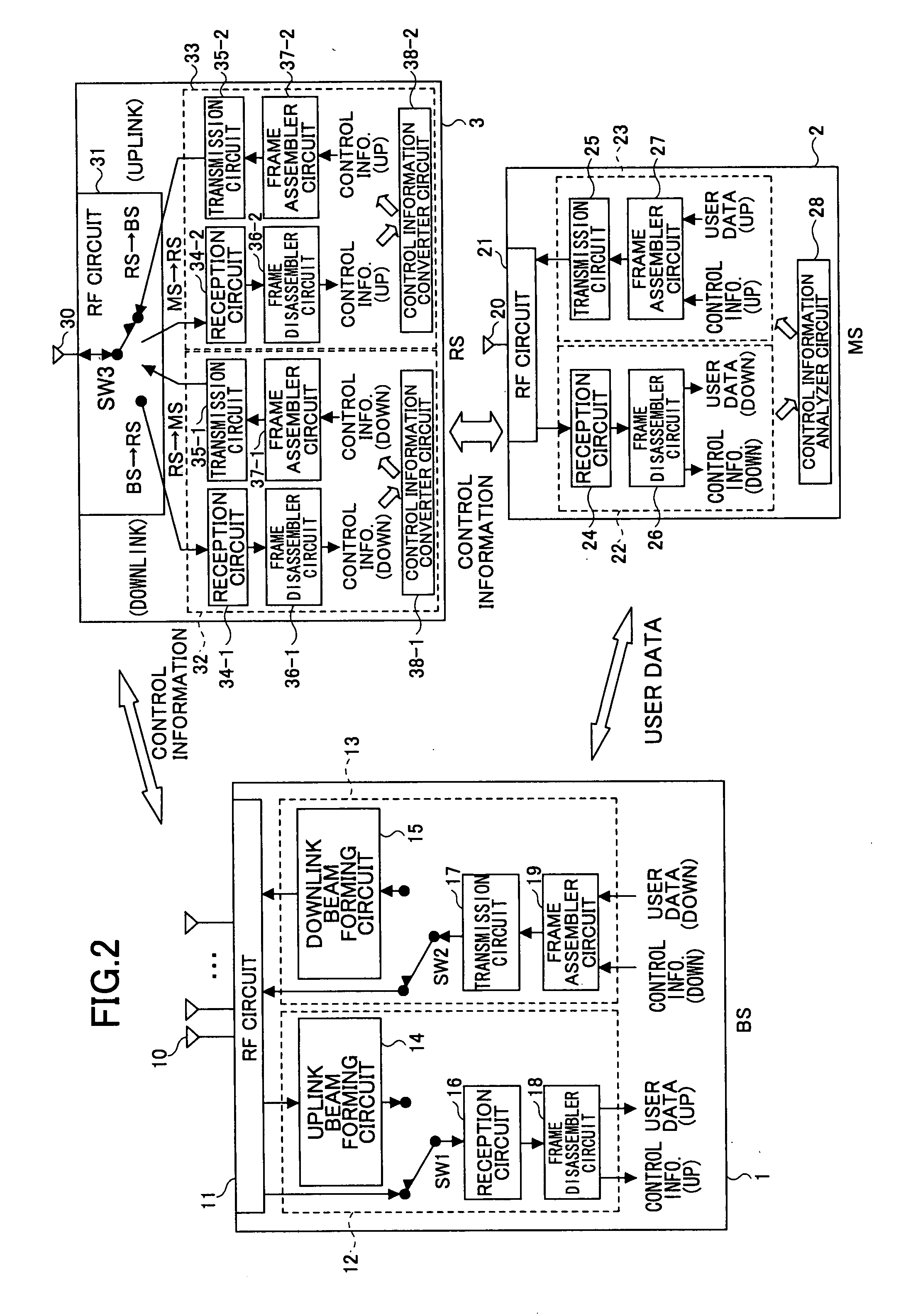
[0039]FIG. 5 is a diagram for illustrating a second embodiment of the present invention. The regular service area a covered by the omnidirectional antenna gain pattern of the BS, the AAS-extended area b, which is an area extended based on the directional adaptive array antenna gain pattern, and the RS-covered area c, which is the service area of the RS, are the same as in the case shown in FIG. 1. Further, the BS, the RS, and the terminal (MS#1) have the same configurations as those shown in FIG. 2. When the BS recognizes (or determines) from response information from the MS#1 through the RS that the MS#1 is positioned in the RS-covered area c, the BS performs control to direct a beam toward the RS. It is requested that the direction of the beam be optimized. For this purpose, the BS causes the beam to scan so as to cover the entire RS-covered area c. The BS is notified of the resulting reception conditions, for example, the measurement results by SINR measurement means, of the MS#1...

third embodiment

[0043]FIG. 7 is a diagram for illustrating a third embodiment of the present invention. The regular service area a covered by the omnidirectional antenna gain pattern of the BS, the AAS-extended area b, which is an area extended based on the directional adaptive array antenna gain pattern, and the RS-covered area c, which is the service area of the RS, are the same as in the case shown in FIG. 1. Further, the BS, the RS, and the terminal (MS#1) have the same configurations as those shown in FIG. 2. When the MS#1 in the RS-covered area c moves to the AAS-extended area b outside the RS-covered area c when the MS#1 is performing communications according to the communication form of Method 3 (BS / RS / MS) of FIG. 6, that is, performing transmission and reception of control information and user data through the RS as indicated by broken arrows as control / data, it is necessary to switch the communication form to Method 1 (BS / MS [beam forming]). In this case, monitoring reception quality in t...


PUM


Abstract

A radio communications system having a radio base station and a radio relay station is disclosed. A terminal performs radio communications through a link with the radio base station or a link with the radio base station via the radio relay station. The radio base station includes an antenna gain pattern switching part configured to switch between an omnidirectional antenna gain pattern and an adaptive array antenna gain pattern forming a beam; and a control part configured to direct the beam to the terminal in one of an extended service area covered by the adaptive array antenna gain pattern outside a regular service area covered by the omnidirectional antenna gain pattern and the service area of the radio relay station by causing the antenna gain pattern switching part to switch to the adaptive array antenna gain pattern.

Description

BACKGROUND OF THE INVENTION[0001]1. Field of the Invention[0002]The present invention relates generally to radio communications systems and radio communications control methods, and more particularly to a radio communications system and a radio communications control method including a radio base station, a radio relay station, and a mobile terminal.[0003]2. Description of the Related Art[0004]There are various known radio communications systems, of which W-CDMA has been in practical use for cellular phones. Further, WiMAX (Worldwide Interoperability for Microwave Access) has also been developed as a high-speed transmission system. Further, adaptive array antenna systems have been known as a technology for improving signal-to-interference-and-noise ratio (SINR) in the radio communications between a radio base station and a mobile or fixed terminal. These adaptive array antenna systems are roughly divided into those using beamforming that has the object of increasing signal power to ...

Claims


Application Information

Patent Timeline
IPC IPC(8): H04B3/36H04B7/14H04J99/00H04W16/24H04W16/28
CPCH04W16/28H04B7/1555H04B7/0617H04B7/026H04W24/10H04W36/30H04W88/08
Inventor YOSHIDA, MAKOTOWATANABE, MASAHIRO
Owner FUJITSU LTD
Why Eureka
Try Eureka