
Heat regenerative mini-turbine generator

a technology of mini-turbine generator and heat-regeneration, which is applied in the direction of steam engine plants, machines/engines, mechanical equipment, etc., can solve the problems of poor efficiency of small-sized turbines, and achieve the effect of poor efficiency and high efficiency

Inactive Publication Date: 2008-02-28
CYCLONE POWER TECH
View PDF5 Cites 53 Cited by
  • Summary
  • Abstract
  • Description
  • Claims
  • Application Information

AI Technical Summary

Benefits of technology

[0004]The present invention provides a heat regenerative mini-turbine generator in a compact, lightweight unit. The unit includes a steam turbine connected to a central shaft that drives a high pressure pump, a high efficiency generator and a blower. An igniter burns fuel exiting a fuel injector to generate heat in a cyclone combustion chamber. Water pumped through coils is heated in the combustion chamber to produce steam energy to drive the turbine. Exhaust steam is directed through a centrifugal condenser having an arrangement of flat plates to condense the steam to a liquid state. The turbine drives the generator, through the conn

Problems solved by technology

However, it is known that turbines in small sizes have poor efficiency.

Method used


Image

  • Heat regenerative mini-turbine generator
  • Heat regenerative mini-turbine generator
  • Heat regenerative mini-turbine generator

Examples


Embodiment Construction

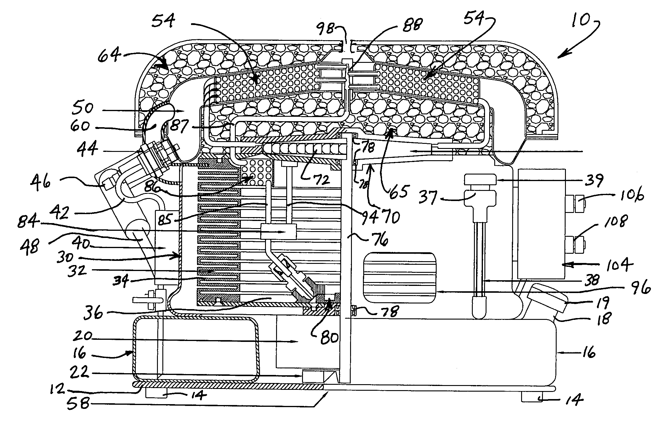
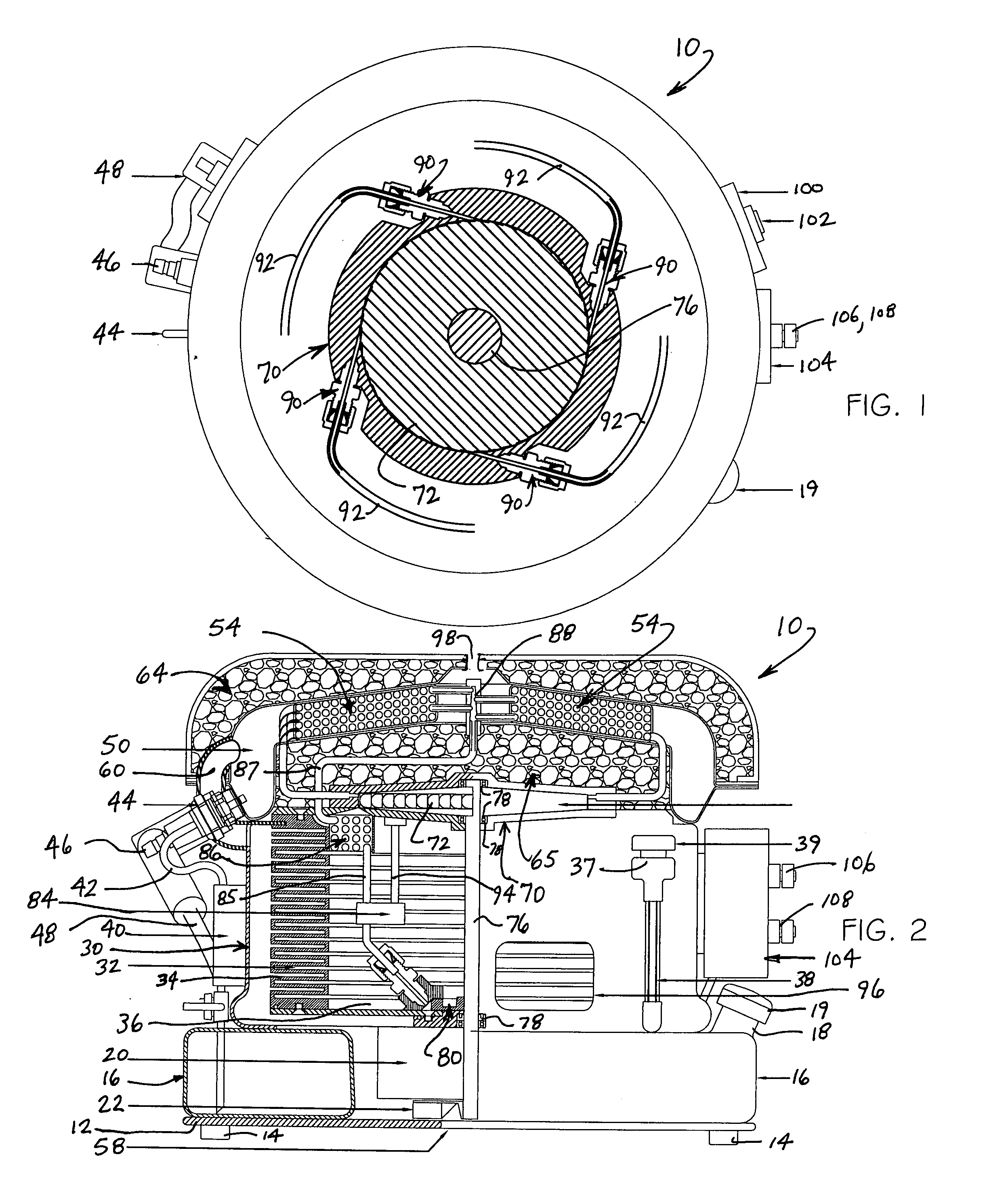
[0010]Referring to the several views of the drawings, and initially FIG. 2, the heat regenerative mini-turbine generator is shown and is generally indicated a 10.

[0011]The generator 10 is supported on a base 12 that may include feet 14 on the bottom for supported engagement on a floor, ground or counter surface. A fuel tank 16 rests on the top of the base. In a preferred embodiment, the fuel tank 16 is circular (i.e. donut shaped) to provide an open central area above the base that accommodates a centrifugal blower 22 and an alternator 20. A fill spout 18 with a cap 19 extends upwardly from the fuel tank to facilitate refilling of fuel.

[0012]A condenser chamber 30 sits above the fuel tank 16 and alternator 20 and contains a centrifugal condenser 32 and a condensate collection pan 36 at the bottom of the condenser chamber. The centrifugal condenser has a spaced arrangement of condenser plates 34 that present a large surface area for maximizing heat transfer within a relatively compac...


PUM


Abstract

A compact, lightweight steam turbine is connected to a central shaft that drives a high pressure pump, a high efficiency generator and a blower. An igniter burns fuel exiting a fuel injector to generate heat in a cyclone combustion chamber. Water pumped through coils is heated in the combustion chamber to produce steam energy to drive the turbine. Exhaust steam is directed through a centrifugal condenser having an arrangement of flat plates to condense the steam to a liquid state. The turbine drives the generator at a high rpm, through the connected shaft, to generate electric power.

Description

BACKGROUND OF THE INVENTION [0001]This non-provisional patent application is based on provisional patent application Ser. No. 60 / 840,786 filed on Oct. 28, 2006.DISCUSSION OF THE RELATED ART [0002]Portable generators for producing electricity are typically powered by combustion engines fueled by gasoline or diesel. Combustion engine powered portable generators are known to be noisy (i.e. loud) and are not fuel efficient. For this reason, portable generators powered by combustion engines are primarily used for emergency power situations when more efficient conventional power sources are unavailable. Additionally, gasoline and diesel powered combustion engines are considerably heavy and bulky. This adds to the overall size and weight of portable generators, making them difficult to transport when used in mobile field operations.[0003]Accordingly, there remains an urgent need for a fuel efficient portable generator that is relatively quiet, compact in size, lightweight and easy to trans...

Claims


Application Information

Patent Timeline
IPC IPC(8): F01K17/04
CPCF01K11/02
Inventor SCHOELL, HARRY
Owner CYCLONE POWER TECH
Features
  • Generate Ideas
  • Intellectual Property
  • Life Sciences
  • Materials
  • Tech Scout
  • Unparalleled Data Quality
  • Higher Quality Content
  • 60% Fewer Hallucinations
Learn More