Pneumatic tire

Inactive Publication Date: 2008-02-28
SUMITOMO RUBBER IND LTD
View PDF4 Cites 37 Cited by
  • Summary
  • Abstract
  • Description
  • Claims
  • Application Information

AI Technical Summary

Benefits of technology

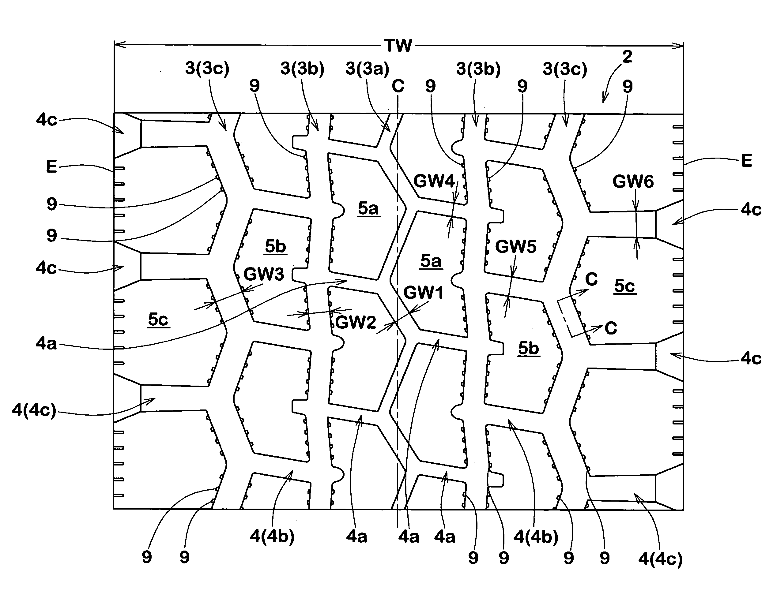
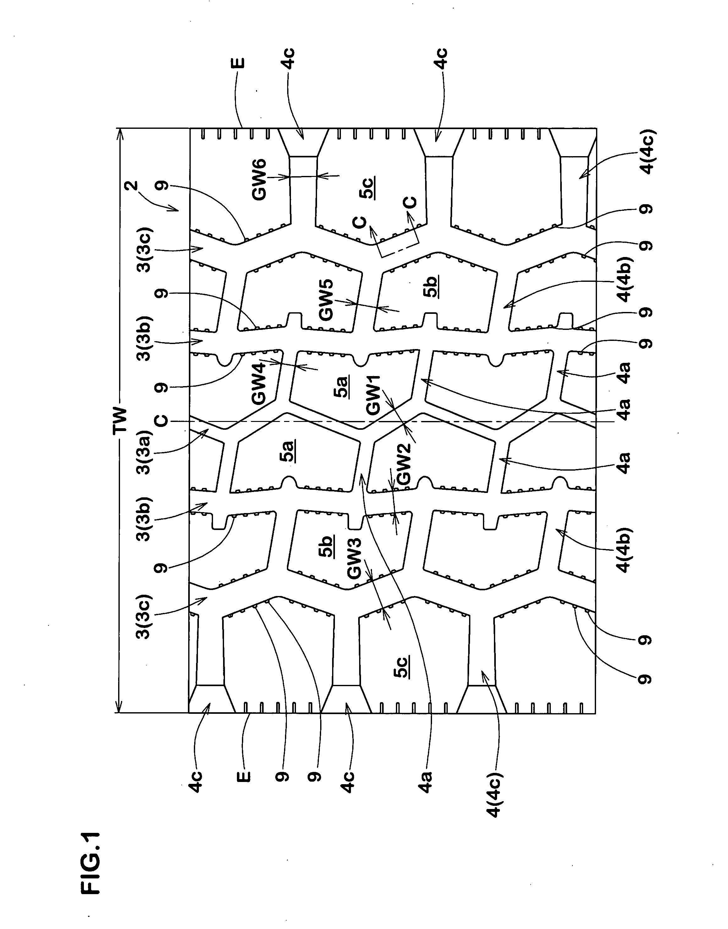
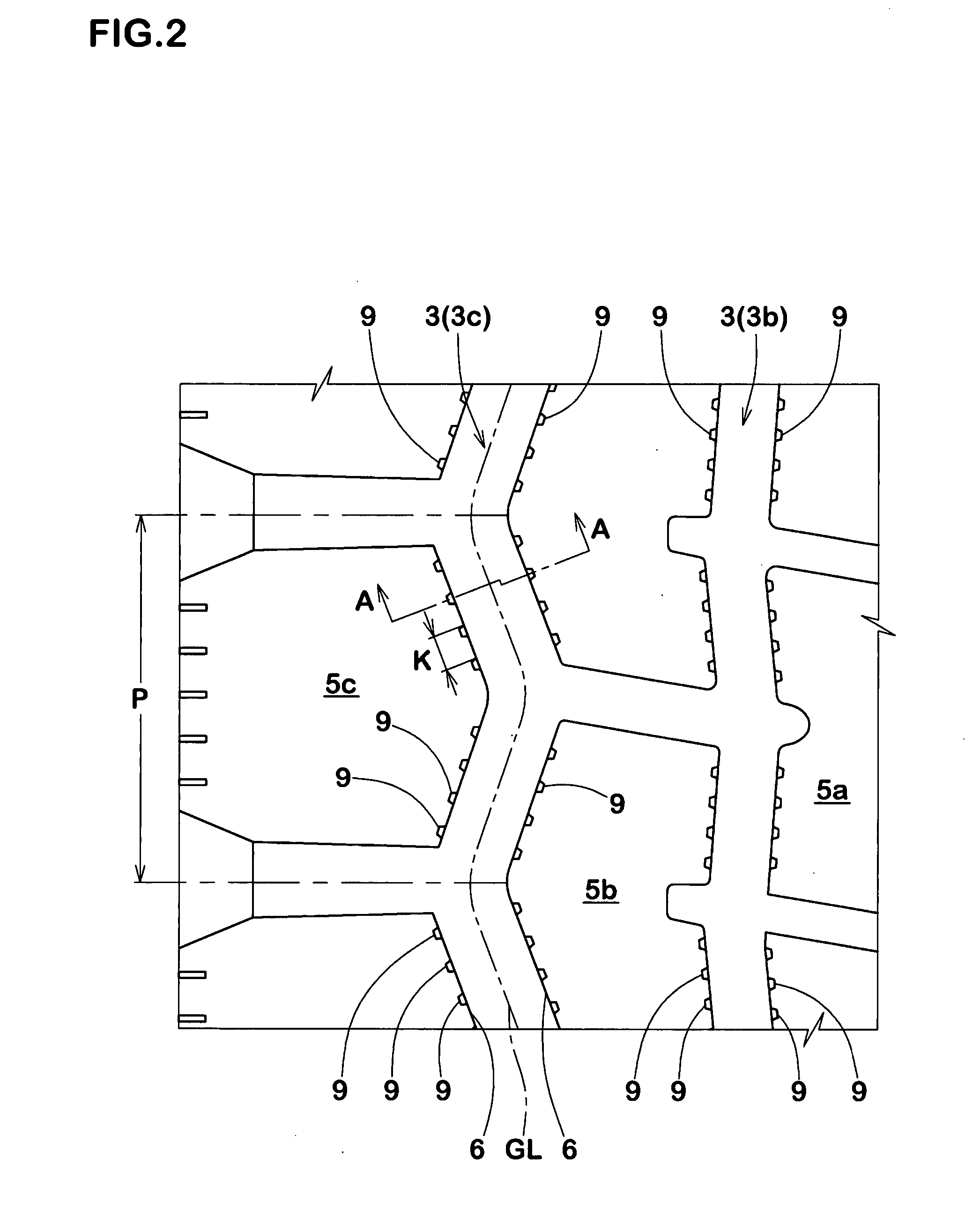
[0014] A plurality of the fine grooves extending in the tire radial direction and having a non-flat surface extending in a wave-like form in its length direction, which are provided in the wall or walls of at least one circumferential groove at intervals in the tire circumferential direction, serves to disturb an air current which generates in the circumferential groove when the tire rotates, to reduce the columnar resonance sound. That

Problems solved by technology

However, such circumferential grooves are easy to generate columnar resonance during running, so the tires tend to be poor in noise performance.
If the width of the circumferential groov

Method used


Image

  • Pneumatic tire
  • Pneumatic tire
  • Pneumatic tire

Examples


examples

[0059] Heavy duty radial tires (size: 11R22.5 14PR) were manufactured based on the specifications shown in Table 1, and tested. The fine grooves formed in these examples were those having a non-flat portion in the form of a zigzag as shown in FIG. 6.

[0060] The performances of the tires were evaluated by the following methods.

[0061] The tires were mounted on each rim (size: 7.50×22.5), inflated to an inner pressure of 800 kPa and attached to all wheels of a ten-ton 2-D truck (non-loaded). The test car was coasted for 50 m distance at a speed of 80 km / h on a test course. The maximum sound level in dB(A) of pass-by noise was measured at the middle point of the test course with a microphone set at 1.2 m height from the road surface and 7.5 m sideways from the running center line. The results are shown as an index based on the result of Comparative Example 1 regarded as 100. The smaller the value, the smaller the pass-by noise.

[0062] The above-mentioned test car was run on an asphalt ...


PUM


Abstract

A pneumatic tire having an improved noise performance without deteriorating the drainage performance and having in a tread portion at least one circumferential main groove 3 which extend continuously in the tire circumferential direction, wherein the circumferential main groove 3 has a pair of groove walls 6, and in at least one of the groove walls 6 are provided at intervals in the tire circumferential direction a plurality of fine grooves 9 each of which extends in the tire radial direction and is provided in at least a part of its inner surface with a non-flat portion 10 extending in a wave-like form in its length direction.

Description

BACKGROUND OF THE INVENTION [0001] The present invention relates to a pneumatic tire having a good noise performance improved without deteriorating a drainage property. [0002] Pneumatic tires are usually provided on its tread portion with one or a plurality of wide circumferential main grooves which extend in the circumferential direction of tire. However, such circumferential grooves are easy to generate columnar resonance during running, so the tires tend to be poor in noise performance. If the width of the circumferential grooves is decreased for the purpose of improving the noise performance, the drainage performance is deteriorated. Like this, the noise performance is repugnant with the drainage performance. [0003] Various proposals to improve these performances have been made. For example, JP-A-2003-146024 discloses a pneumatic tire in which for the purpose of improving the wet grip performance without impairing the noise performance, at least one corner between the tread surf...

Claims


Application Information

Patent Timeline
IPC IPC(8): B60C11/03
CPCB60C11/0309B60C2011/0383Y10S152/03Y10S152/902B60C2011/133B60C2011/1231
Inventor YOSHIKAWA, HIDEAKITAMURA, MASAHIRO
Owner SUMITOMO RUBBER IND LTD
Why Eureka
Try Eureka